Chapter 3 - Robot Installation
40 Adept Cobra s600/s800 Robot User’s Guide, Rev H
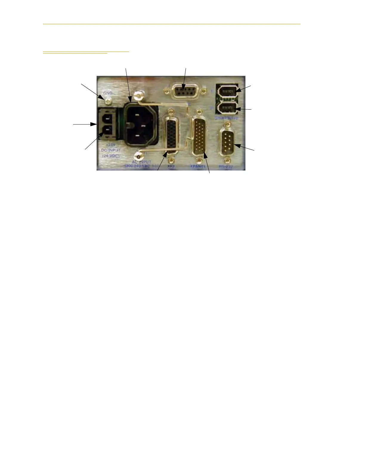
3.6 Description of Connectors on Robot Interface Panel
Figure 3-3. Robot Interface Panel
24 VDC - for connecting user-supplied 24 VDC power to the robot. The mating connector
is provided.
Ground Point - for connecting cable shield from user-supplied 24 VDC cable.
200/240 VAC - for connecting 200-240 VAC, single-phase, input power to the robot. The
mating connector is provided.
XSLV - for connecting the supplied XSYS cable from the controller XSYS connector. (DB-9,
female)
SmartServo 1/2 - for connecting the IEEE 1394 cable from the controller (SmartServo 1.1)
to the robot upper connector (SmartServo 1). The robot lower connector (SmartServo 2)
can be used to connect to a second robot or another 1394-based motion axis.
RS-232 - used only with Cobra i-series robots, for connecting a system terminal. (DB-9,
male)
XPANEL - used only with Cobra i-series robots, for connecting the front panel and MCP.
(DB26, high density, male)
XIO - for user I/O signals for peripheral devices. This connector provides 8 outputs and
12 inputs. See Section 5.5 on page 59 for connector pin allocations for inputs and outputs.
That section also contains details on how to access these I/O signals via V+. (DB26, high
density, female)
24 VDC
Input
200-240 VAC
XSLV
XIO
XPANEL
RS-232
SmartServo Port 1
+24 VDC
Pin
Ground
Point
SmartServo Port 2
 Loading...

