Chapter 7 - Optional Equipment Installation
92 Adept Cobra s600/s800 Robot User’s Guide, Rev H
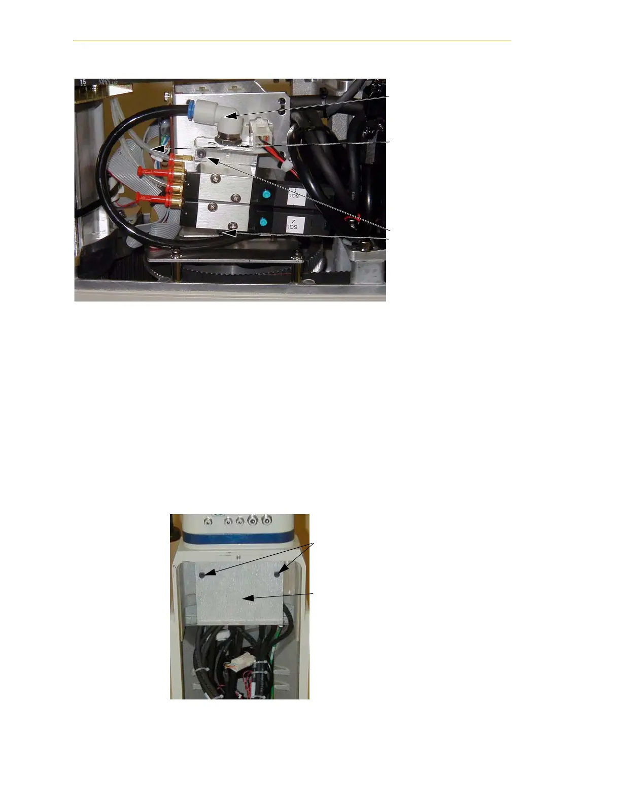
Figure 7-9. Solenoid Placement Using Mounting Hardware
9. Install the appropriate lengths of 5/32 inch plastic tubing (supplied) into the two
output ports on the manifold.
• Route the tubing up along the tower bracket next to the quill and down
through the center of the quill.
• Use cable ties as needed to secure the tubing.
10. Loosen the securing screw on the AIB chassis, and lower the chassis down flat.
See Figure 6-2 on page 74 for the location of the securing screw.
11. Remove the cable strap plate by removing two screws and split washers. See
Figure 7-10. This allows the harness to move when you lift the J1 cover in the next
step.
Figure 7-10. Removing the Cable Strap Plate
Air intake coupling
with spare air line
installed
Tubing connected
to output port
Mounting screws for
solenoid assembly
Two M5 x 8 screws
Cable Strap Plate

 Loading...
