Chapter 4 - System Installation
48 Adept Cobra s600/s800 Robot User’s Guide, Rev H
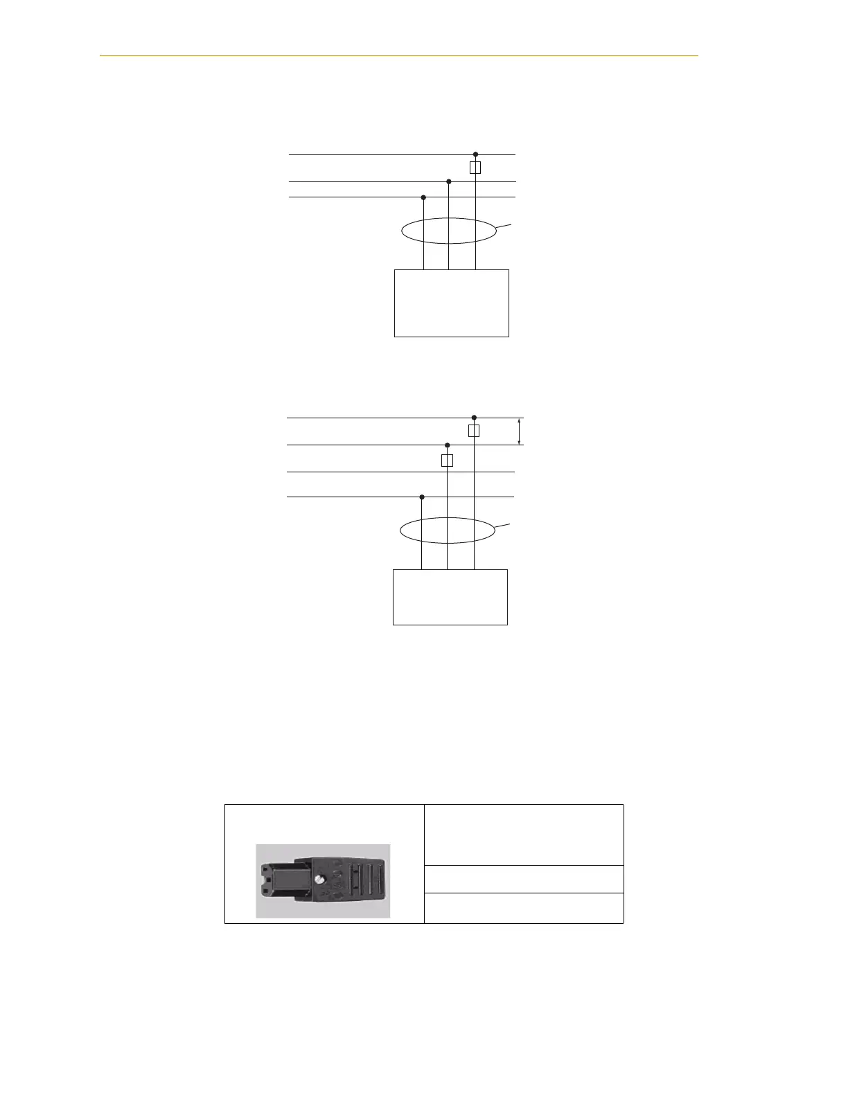
AC Power Diagrams
Figure 4-3. Typical AC Power Installation with Single-Phase Supply
Figure 4-4. Single-Phase AC Power Installation from a Three-Phase AC Supply
Details for AC Mating Connector
The AC mating connector is supplied with each system. It is typically shipped in the
cable/accessories box. The supplied plug is internally labeled for the AC power
connections (L, E, N).
NOTE: The AC power cable is not supplied with the system, but is
available in the optional Power Cable kit; see Table 4-1 on page 42.
Table 4-7. AC Mating Connector Details
AC Connector details AC in-line power plug,
straight, female, screw
terminal, 10 A, 250 VAC
Qualtek P/N 709-00/00
Digi-Key P/N Q217-ND
E
E
N
N
L
L
F1 10A
Adept Cobra
s600/s800 and
i600/i800 Robots
1Ø 200–240VAC
User-Supplied
AC Power Cable
Note: F1 is user-supplied, must be slow blow.
1Ø
200–240VAC
20A
L = Line
N = Neutral
E = Earth Ground
E
E
N
L3
L
L1
L2
F5 10A
F4 10A
Adept Cobra
s600/s800 and
i600/i800Robots
1Ø 200–240VAC
User-Supplied
AC Power Cable
Note: F4 and F5 are user-supplied, must be slow blow.
3Ø
200–240VAC
L = Line 1
N = Line 2
E = Earth Ground
200–240VAC
 Loading...

