Internal User Connectors
Adept Cobra s600/s800 Robot User’s Guide, Rev H 85
SOLND Connector
This 4-pin connector provides the output signals for the optional Robot Solenoid Kit. See
Table 7-1 and Figure 7-5 on page 84. See Section 7.6 on page 90 for installation details.
OP3/4 Connector
This 4-pin connector (see Figure 7-4 on page 84) provides the output signals for a second
set of optional robot hand valve solenoids, or other user-supplied devices. See Table 7-2
and Figure 7-6 on page 86.
Table 7-1. SOLND Connector Pinout
Pin # Description Pin Location
1
Output 3001 (signal 9 in
Cobra i600/i800 robots)
SOLND Connector
as viewed on robot
2 Ground
3
Output 3002 (signal 10 in
Cobra i600/i800 robots)
4 Ground
Mating Connector:
AMP/Tyco #172167-1, 4-pin Mini-Universal Mate-N-Lok
AMP/Tyco #770985-1, Pin Contact, Mini-Univ. Mate-N-Lok
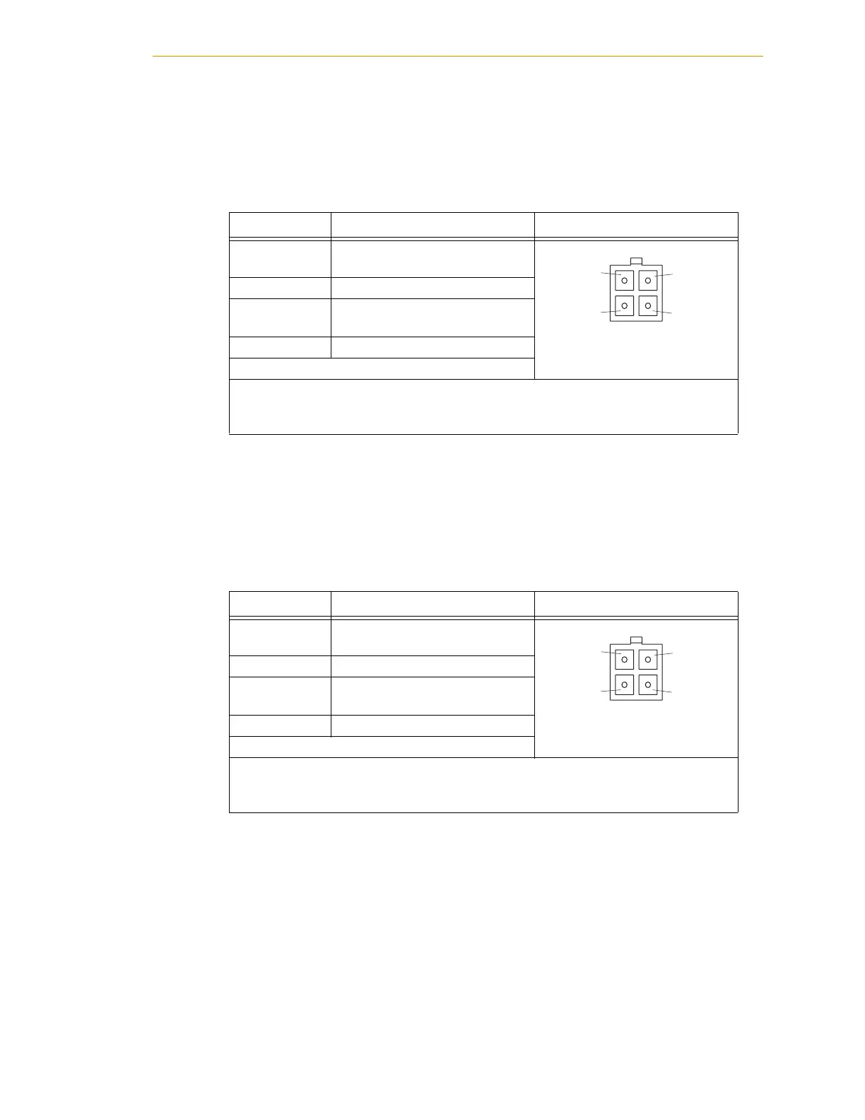
Table 7-2. OP3/4 Connector Pinout
Pin # Description Pin Location
1
Output 3003 (signal 11 in
Cobra i600/i800 robots)
OP3/4 Connector
as viewed on robot
2 Ground
3
Output 3004 (signal 12 in
Cobra i600/i800 robots)
4 Ground
Mating Connector:
AMP/Tyco #172167-1, 4-pin Mini-Universal Mate-N-Lok
AMP/Tyco #770985-1, Pin Contact, Mini-Univ. Mate-N-Lok
1
2
4
3
1
2
4
3
 Loading...

