Chapter 3 - Robot Installation
38 Adept Cobra s600/s800 Robot User’s Guide, Rev H
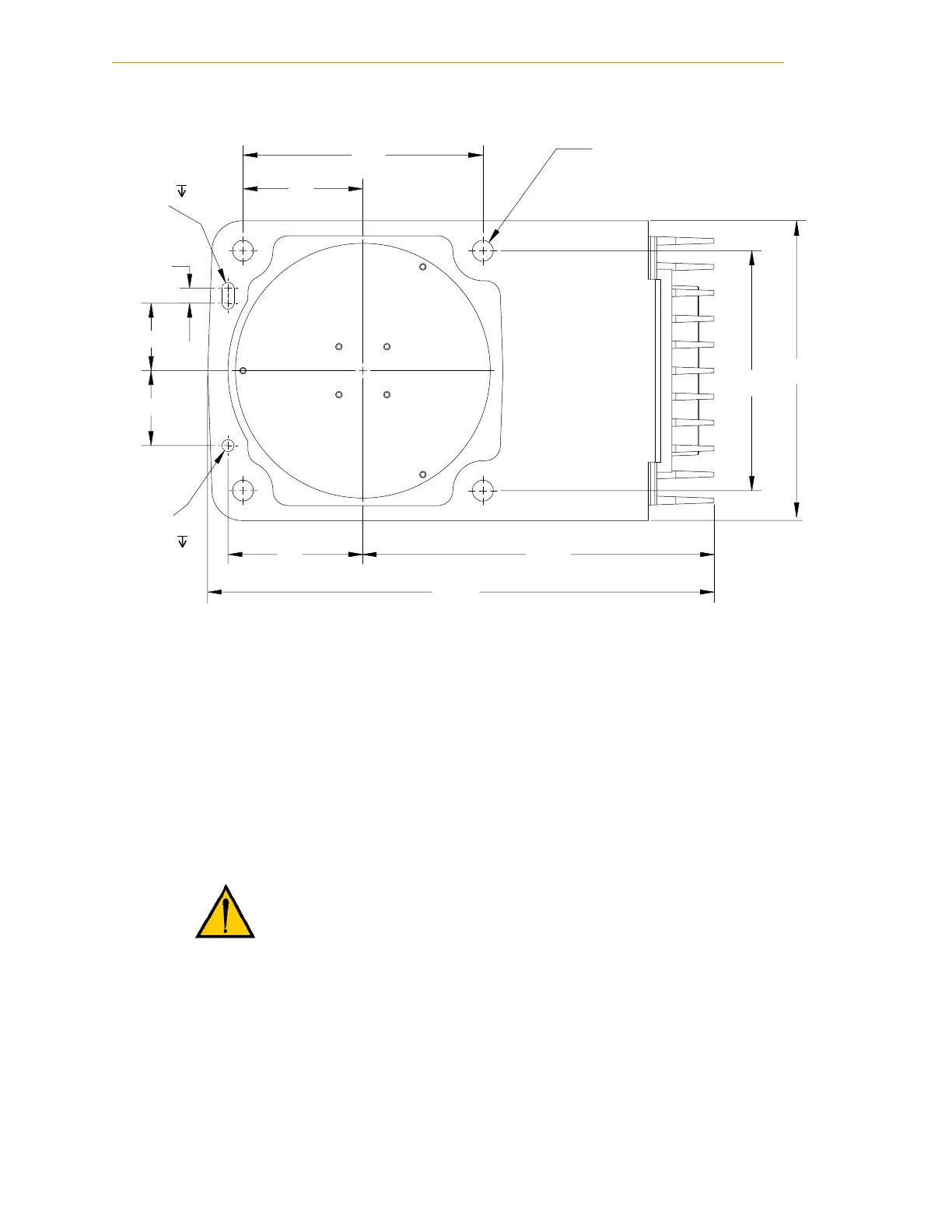
Figure 3-2. Mounting Hole Pattern for Robot
Robot Mounting Procedure
1. Using the dimensions shown in Figure 3-2, drill and tap the mounting surface for
four M12 - 1.75 x 36 mm (or 7/16 - 14 UNC x 1.50 in.) machine bolts (bolts are
user-supplied). See Table 3-2 for bolt and torque specifications.
2. While the robot is still bolted to the transportation pallet, connect the hydraulic
lift to the eyebolt at the top of the inner link (see Figure 3-1 on page 35). Take up
any slack, but do not lift the robot at this time.
3. Remove the four bolts securing the robot base to the pallet. Retain these bolts for
possible later relocation of the equipment.
4. Lift the robot and position it directly over the mounting surface.
WARNING: Do not attempt to lift the robot at any points
other than the eyebolt provided. Do not attempt to extend
the inner or outer links of the robot until the robot has
been secured in position. Failure to comply could result in
the robot falling and causing either personnel injury or
equipment damage.
+
.
1
4
1
1
1
2
+
.
1
14 THR
2

 Loading...
