Chapter 7 - Optional Equipment Installation
82 Adept Cobra s600/s800 Robot User’s Guide, Rev H
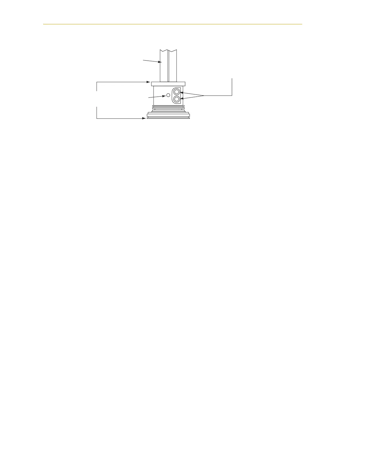
Figure 7-1. Tool Flange Removal Details
Installing the Flange
1. Make sure the steel ball is in the setscrew hole inside the flange. Hold it in place
with your finger as you get ready to install the flange.
2. Slide the flange up on the quill shaft as far as it will go, and rotate until the
setscrew is lined up with the original vertical groove.
3. Support the flange while using a 2.5 mm Allen wrench to tighten the setscrew to
finger tight. Do not over-tighten the setscrew because this will cause the flange to
be off-center from the quill shaft.
4. Use a socket driver to tighten one of the socket-head screws part of the way, then
tighten the other one the same amount. Alternate between the two screws so there
is even pressure on both once they are tight. The torque specification for each
screw is 8 N•m (70 in-lb).
User flange
assembly
Setscrew
M4 Socket-head
cap screws
Quill shaft
 Loading...

