Connecting Digital I/O to a Dual Robot System
Adept Cobra s600/s800 Robot User’s Guide, Rev H 135
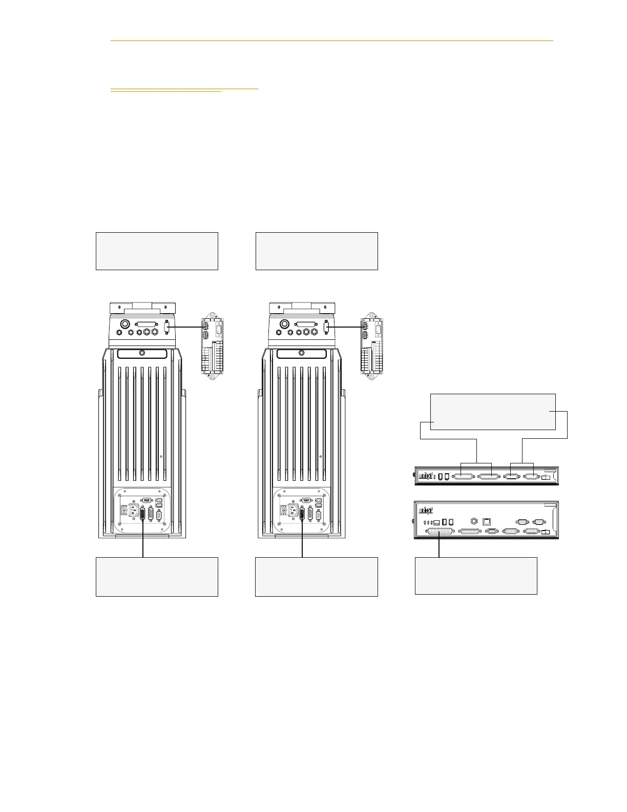
11.3 Connecting Digital I/O to a Dual Robot System
You can connect digital I/O to a dual robot system as shown in Figure 11-2. The default
signal configuration, or mapping, is shown in Table 11-1 on page 136. This configuration
is usually sufficient for most installations. If you need to add more I/O, or change the
mapping, see Section 11.4 and Section 11.5.
NOTE: With the release of V+ 16.1 F6 in January 2005, the default signal
configuration for digital I/O was changed to the values shown in Figure
11-2 and Table 11-1 on page 136.
Figure 11-2. Digital I/O Connections to a Dual Robot System
SF
IEEE-1394
X2
SC-DIO
LINK
*S/N 3563-XXXXX*
X1
24V 0.5A
R
OK
X4
- + - +
1.1 1.2
XDC1 XDC2
X3
1 2 3
RS-422/485
XUSR
XSYS
SF
XMCP
1.1
SmartController CS
LANHPE
OFF
24V 5A
ON
RS-232/TERM
XFP
HDES
XDIO
Eth 10/100
*S/N 3561-XXXXX*
SW1
Device Net
IEEE-1394
XDC1 XDC2
- + - +
1 2 3 4
OK
R
1.2
GND
XSLV
1
2
SmartServo
RS-232
XPANEL
AC INPUT
(200-240 VAC 1Φ)
+24V
DC INPUT
(24 VDC)
XIO
GND
XSLV
1
2
SmartServo
RS-232
XPANEL
AC INPUT
(200-240 VAC 1Φ)
+24V
DC INPUT
(24 VDC)
XIO
Optional
sDIO #1
SmartController
Robot #2
Optional
IO Blox Device
XIO Connector on Robot #2
12 Input signals: 1145 to 1156
8 Output signals: 0137 to 0144
XDIO Connector
12 Input signals: 1001 to 1012
8 Output signals: 0001 to 0008
IO Blox #1 on Robot #2
8 Input signals: 1161 to 1168
8 Output signals: 0145 to 0152
sDIO #1
32 Input signals: 1033 to 1064
32 Output signals: 0033 to 0064
Robot #1
Optional
IO Blox Device
XIO Connector on Robot #1
12 Input signals: 1097 to 1108
8 Output signals: 0097 to 0104
IO Blox #1 on Robot #1
8 Input signals: 1113 to 1120
8 Output signals: 0105 to 0112
 Loading...

