Chapter 11 - Dual Robot Systems
136 Adept Cobra s600/s800 Robot User’s Guide, Rev H
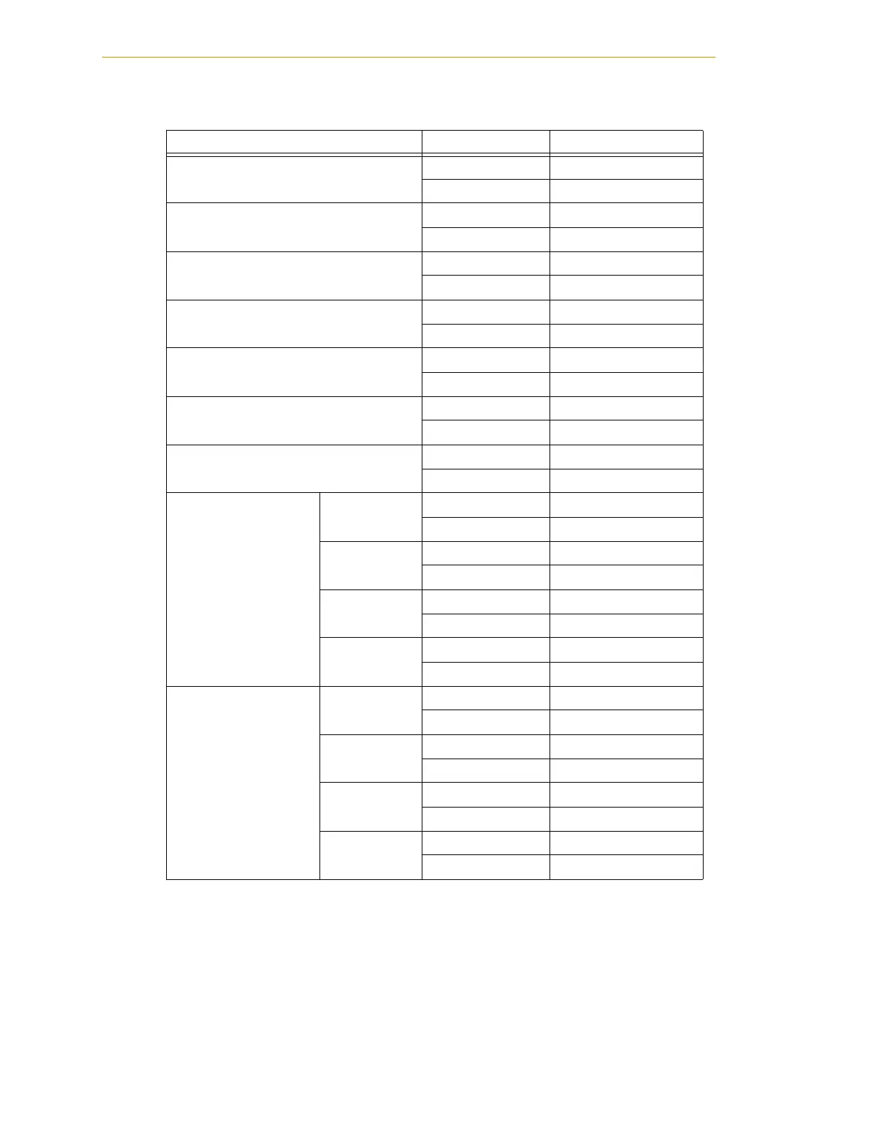
Table 11-1. Default Digital I/O Signal Configuration, Dual Robot System
Location Type Signal Range
Controller XDIO connector Inputs 1001 - 1012
Outputs 0001 - 0008
sDIO Module 1 Inputs 1033 - 1064
Outputs 0033 - 0064
sDIO Module 2 Inputs 1065 - 1096
Outputs 0065 - 0096
sDIO Module 3
(recommended
a
)
a
For sDIO modules 3 and 4, you must configure the signals using CONFIG_C, to
have the system support those modules. See the Adept SmartController User’s
Guide for additional information on that process.
Inputs 1201 - 1232
Outputs 0201 - 0232
sDIO Module 4
(recommended
a
)
Inputs 1233 - 1264
Outputs 0233 - 0264
Robot 1 XIO connector Inputs 1097 - 1108
Outputs 0097 - 0104
Robot 2 XIO connector Inputs 1145 - 1156
Outputs 0137 - 0144
Robot 1 IO Blox 1 Inputs 1113 - 1120
Outputs 0105 - 0112
IO Blox 2 Inputs 1121 - 1128
Outputs 0113 - 0120
IO Blox 3 Inputs 1129 - 1136
Outputs 0121 - 0128
IO Blox 4 Inputs 1137 - 1144
Outputs 0129 - 0136
Robot 2 IO Blox 1 Inputs 1161 - 1168
Outputs 0145 - 0152
IO Blox 2 Inputs 1169 - 1176
Outputs 0153 - 0160
IO Blox 3 Inputs 1177 - 1184
Outputs 0161 - 0168
IO Blox 4 Inputs 1185 - 1192
Outputs 0169 - 0176
 Loading...

