Installing Adjustable Hardstops
Adept Cobra s600/s800 Robot User’s Guide, Rev H 101
Installation Procedure
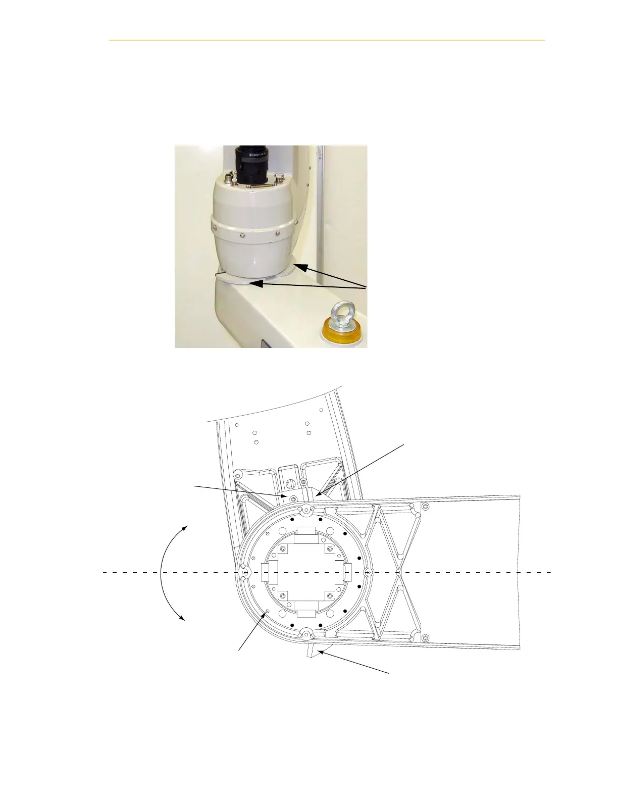
1. Slide the two adjustable hardstop plates into the space between inner and outer
links. See Figure 7-21. Looking up at the inner link from underneath, align the
holes in the plates with the holes in the inner link - see Figure 7-22 on page 101.
Figure 7-21. Joint 2 Adjustable Hardstop Locations
Figure 7-22. Screw Locations for Joint 2 Adjustable Hardstops
Joint 2 Adjustable
Hardstop Plates Installed
in Position 1.
12 thru holes for M5 x 10 screws,
for installing Joint 2 hardstops, located
30 degrees apart
Joint 2 Left Hardstop Plate,
installed in +81 degree position
Joint 2 Fixed
Hardstop Device
Joint 2
Positive
direction
Joint 2
Negative
direction
Joint 2 Right Hardstop Plate,
installed in -81 degree position
+
_
View of under side of Inner Link, looking up

 Loading...
