ADAM-6200 User Manual 114
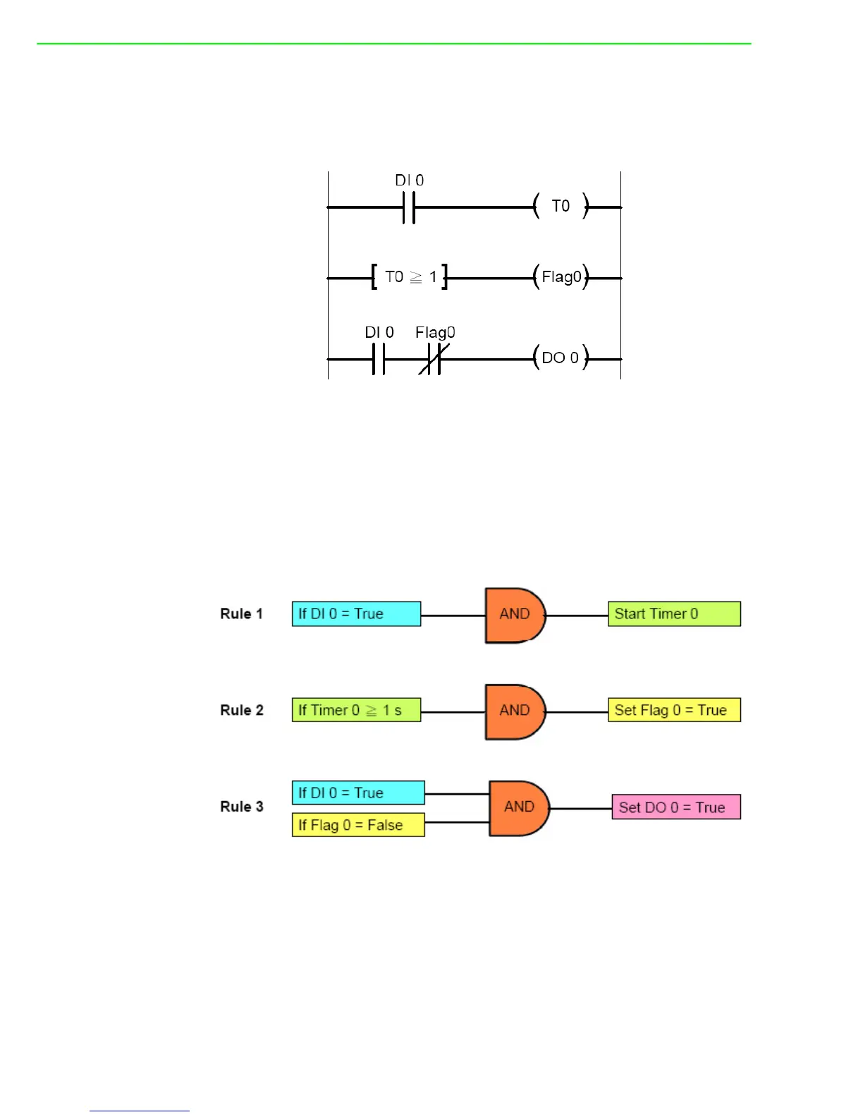
You can see that DO 0 will only be triggered when rising edge of DI 0 occurs. In the
example project we provide, the DO status will remain logic high for 1 second. Then it
will back to logic low. When PLC is used for this kind of application, the ladder dia-
gram will be likely as below:
When you use GCL to achieve rising edge application, 3 logic rules, 1 Internal Timer
(Timer 0) and 1 Internal Flag (Flag 0) are needed. For example, with logic rule 3, DO
0 value is controlled by DI 0 and Flag 0. Flag 0 is initially set as False. When rising
edge occurs (DI value changes from logic low to logic high), DO will be activated
(logic rule 3 are satisfied), and Timer 0 starts to count time (logic rule 1 are satisfied).
After Timer 0 counts up to the specific time interval (1 second), Flag 0 will become
logic True by logic rule 2, making DO 0 value logic low (logic rule 3 are not satisfied).
The GCL architecture is similar to the ladder diagram.
 Loading...