a) Apply a thin layer of marking paint on the under side of the cylinder liner flange.
b) Fit the cylinder liner without O-rings and turn the cylinder liner forward and backward.
c) Lift out the cylinder liner.
d) Check that the paint has spread evenly on the whole contact surface.
3.
Use a milling cutter, if the recess of the
cylinder liner is damaged or the cylinder liner
height needs to be adjusted.
4.
Do light lapping after milling with the help of
the cylinder liner, if needed.
a) Apply lapping paste to the under side of
the cylinder liner flange.
b) Twist the liner with twisting tool
Lapping is not correct working method for
adjusting the cylinder liner height.
5.
Clean the contact surfaces.
6.
Fit the cylinder liners for measuring.
a) Press the cylinder liners into the cylinder
block.
b) Fit each cylinder liner with two press
tools.
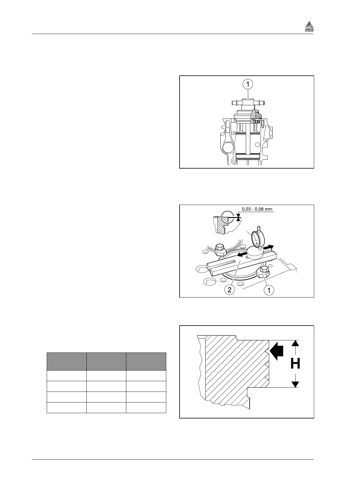
Fig. 10
(1) Milling cutter 9101 65600 Milling cutter 9104
52000 (84 and 98 engines)
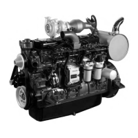
7.
Measure the cylinder liner height with a dial
gauge and holder.
a) Zero the dial gauge against a flat surface,
for example, the cylinder block face.
b) Measure each liner in four locations.
• The height of the cylinder liner above the
cylinder block face can be 0.03 - 0.08
mm.
• The height difference between cylinder
liners under the same cylinder head must
not be more than 0.02 mm.
• An intermediate cylinder liner must not be
lower than an outer one.
Fig. 11
(1) Press tools 9101 66300
(2) Dial gauge and holder 9025 79200
8.
Fit a cylinder liner with a higher flange, if the
cylinder liner height is too low.
33-74 engines
H Marking
grooves pcs
Order
number
9.03+0.02 - (std.) 8366 73191
9.08+0.02 1 8366 47933
9.13+0.02 2 8366 47934
9.23+0.02 3 8366 47935
84-98 engines
Fig. 12
3. Maintenance
3-10 4th Generation Engines
8370 79492