Chapter 3 Methods and Mappings 61
USG-CUS-059 Rev05MassARRAY® Nanodispenser RS1000 v2.1 User Guide
For Research Use Only. Not for use in diagnostic procedures.
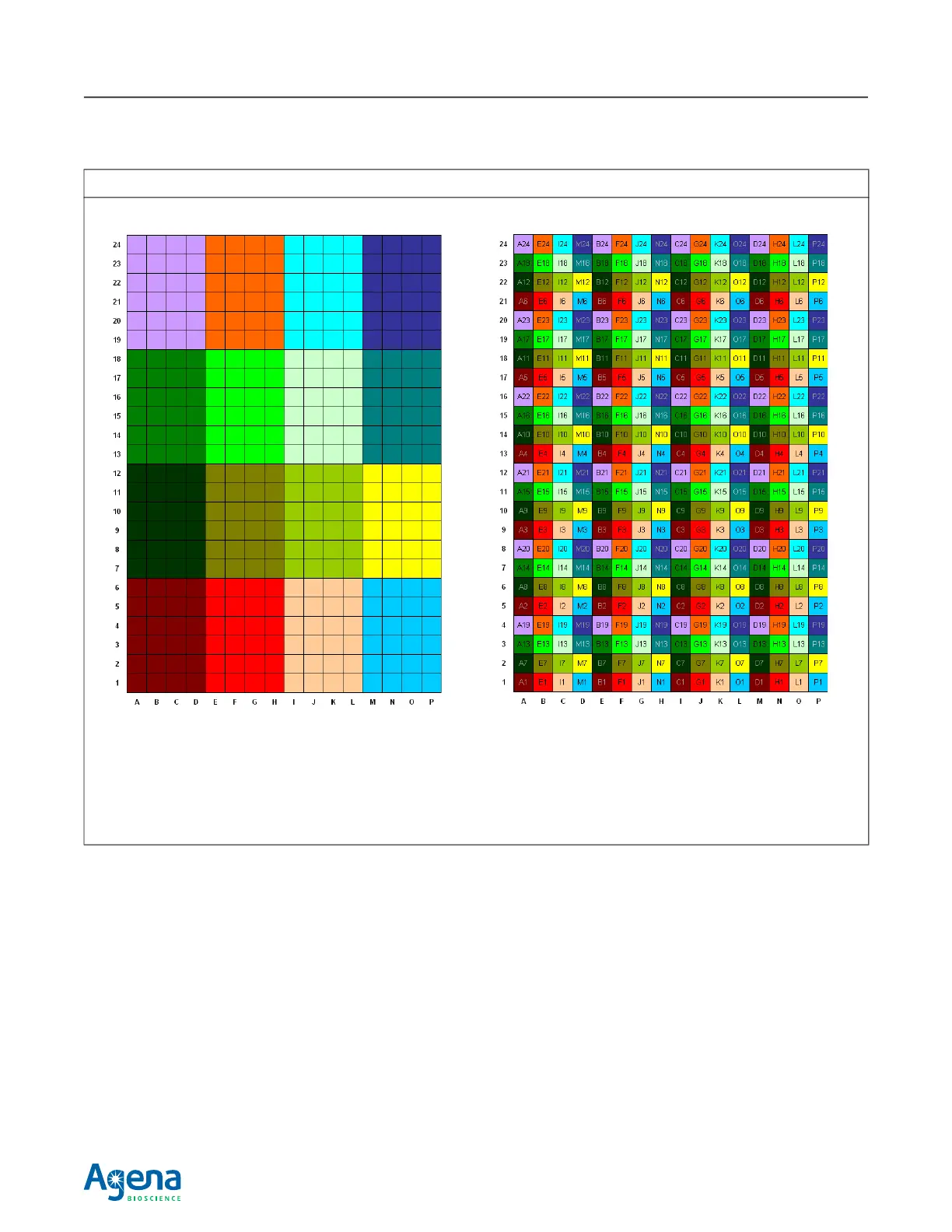
Figure 3.3 384 Plate to 384 SpectroCHIP Array Plate-to-SpectroCHIP Array Mapping
384-well microtiter plate 384 SpectroCHIP Array
Each cell in this diagram represents a plate well. The 24-
pin array is designed to fit into a 4 X 6 group of
contiguous wells. In this diagram, 4 X 6 groups are color-
coded to indicate that analytes in wells of the same color
are loaded in the same load cycle.
Each cell in this diagram represents a SpectroCHIP Array
pad. Each pad is labeled with the number of the plate well
from which it receives analyte. Note that the pins are
spaced so they land on every fourth pad; a 4 X 6 group of
plate wells is spread out across every fourth SpectroCHIP
Array pad.