Inlets 3
Advanced Operation Manual 49
These numbers are based on the resistance to flow of new,
clean inlet systems. Sample condensation in the split vent
tube or a dirty filter can make these values non- attainable.
Selecting the correct S/SL inlet liner
Split liner
A good liner for split mode operation will offer very little
restriction to the split flow path between the bottom of the
liner and the inlet gold seal and between the outside of the
liner and the inside of the injection port body. The preferred
Agilent split liner, part number 5183- 4647, incorporates a
glass positioning bead on the bottom to facilitate this. It will
also incorporate glass wool or some other source of surface
area inside the liner that provides for complete sample
vaporization across the boiling point range of the sample.
Select an appropriate liner from Table 7.
Tabl e 6 Approximate minimum viable inlet pressures for split/splitless inlet in split mode, in psi (kPa)
Split vent flow (mL/min)
50–100 100–200 200–400 400–600
Helium and hydrogen carrier gases
Split liners - 5183-4647, 19251-60540 2.5 (17.2) 3.5 (24.1 4.5 (31) 6.0 (41.4)
Splitless liners - 5062-3587, 5181-8818 4.0 (27.6) 5.5 (37.9) 8.0 (55.2) 11.0 (75.4)
Nitrogen carrier gas
Split liners - 19251-60540, 5183-4647 3.0 (20.7) 4.0(27.6) — —
Splitless liners - 5062-3587, 5181-8818 4.0 (27.6) 6.0 (41.4) — —
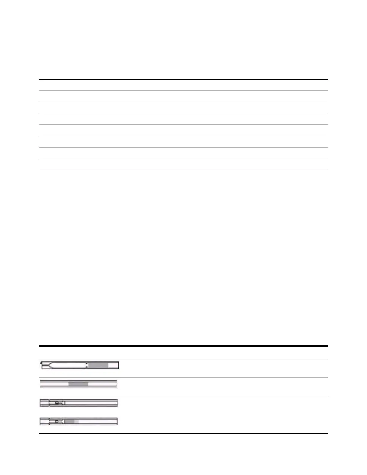
Tabl e 7 Split mode liners
Liner Description Volume Mode Deactivated Part Number
Low Pressure Drop
– Positioning Bead
870 µL Split – Fast
Injection
Yes 5183-4647
4mm ID, Glass Wool 990 µL Split – Fast
Injection
No 19251-60540
Empty Pin & Cup 800 µL Split – Manual
Only
No 18740-80190
Packed Pin & Cup 800 µL Split – Manual
Only
No 18740-60840

 Loading...