20 Advanced Operation Manual
2 Flow and Pressure Modules
About Flow and Pressure Control
The GC uses four types of electronic flow or pressure
controllers; inlet modules, detector modules, pressure control
modules (PCMs), and auxiliary pressure controllers (Aux
EPCs).
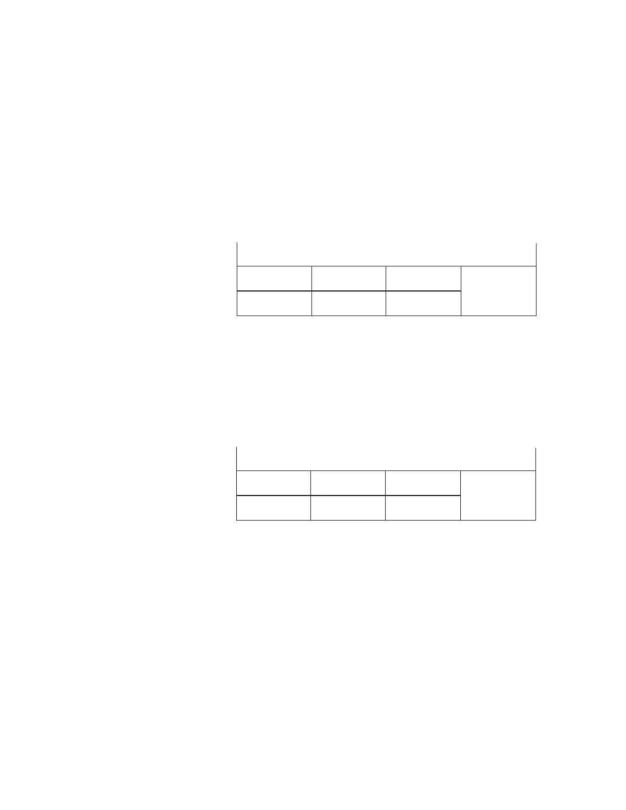
All of these modules mount in the slots at the top rear of
the GC. The slots are identified by numbers, as shown here.
When a module is installed in a slot, it must be connected to
the communications buss that runs underneath it. Each
branch of the buss has an identifying label near the
connector. The proper branch must be connected to the
module for the firmware to recognize it.
Branch/slot assignments are:
If a detector is mounted in the left side carrier (as seen
from the front side of the oven), it is controlled by EPC6. An
extension cable connects to EPC6, runs across the top of the
oven just in front of the top row of slots, and passes through
an opening into the detector carrier.
Maximum operating pressure
The pneumatics modules of the GC will stand over 250 psi
pressure, but may not function reliably. We recommend a
maximum continuous operating pressure of 170 psi to avoid
excessive wear and leaks.
Split vent traps
and valves
Back of GC
Slot 1
Slot 2
Slot 3
Slot 4
Slot 5
Slot 6
Split vent traps
and valves
Back of GC
EPC1
EPC2
EPC3
EPC4
EPC5
EPC6

 Loading...