42 Advanced Operation Manual
3 Inlets
About Heaters
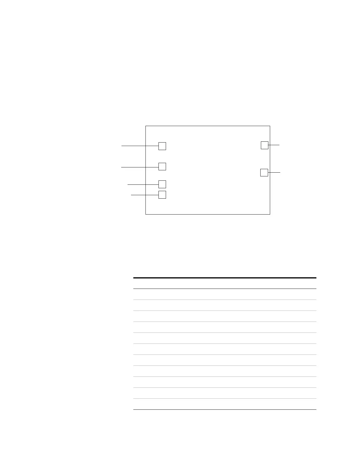
Inlets (and detectors, valve boxes, etc.) are heated. There are
six heater connectors on the GC mainframe, located as
shown here:
All heater connectors are square, 4- conductor receptacles
mounted on brackets.
The next table describes the heater locations that are
available for each module.
1
2
3
4
5
6
Front of GC
Near front inlet
Near back inlet
Near top right corner
of front detector board
Near top right corner
of back detector board
Left end of valve bracket
Right end of valve bracket
Tabl e 5 Heater connection locations by module
Module Available heater connection location
Front inlet 1 or None
Back inlet 2 or None
Front detector 3 or 5
Back detector 4 or 6
Aux detector 1 5 or 6 or 2
Aux detector 2 None
PCM A 5 or 6 or 1 or 2
PCM B 5 or 6 or 1 or 2
PCM C 5 or 6 or 1 or 2
AUX 1,2,3 None
AUX 4,5,6 None

 Loading...