6- 45
Calibrating for Increased Measurement Accuracy
Calibrating for Noninsertable Devices
Verify the Results
Since the effect of the adapter has been removed, it is easy to verify the accuracy of the technique by simply
measuring the adapter itself. Because the adapter was used during the creation of the two cal sets, and the
technique removes its effects, measurement of the adapter itself should show the S-parameters.
If unexpected phase variations are observed, this indicates that the electrical delay of the adapter was not
specified within a quarter wavelength over the frequency range of interest. To correct this, recall both cal
sets, since the data was previously stored to disk, change the adapter delay, and press
.
Your analyzer’s programmer’s guide contains an example program that demonstrates the adapter removal
process over GPIB.
Matched Adapters
With this method, you use two precision matched adapters which are "equal." To be equal, the adapters
must have the same match, Z
0
, insertion loss, and electrical delay. The adapters in most Agilent calibration
kits have matched electrical length, even if the physical lengths appear different.
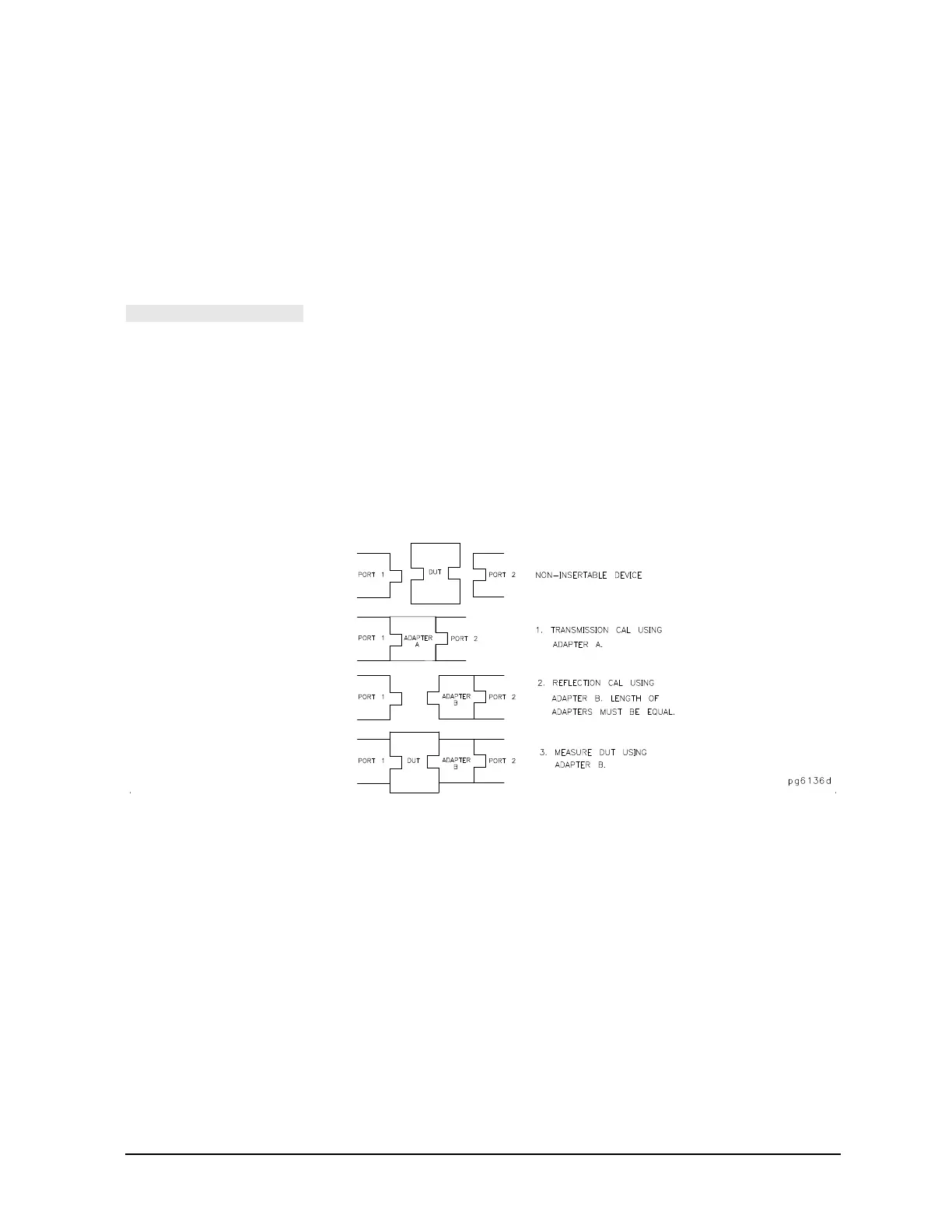
Figure 6-18 Calibrating for Noninsertable Devices
To use this method, refer to Figure 6-18 and perform the following steps:
1. Perform a transmission calibration using the first adapter.
2. Remove adapter A, and place adapter B on port 2. Adapter B becomes the effective test port.
3. Perform a reflection calibration.
4. Measure the test device with adapter B in place.
The errors remaining after calibration with this method are equal to the differences between the two
adapters that are used.
Modify the Cal Kit Thru Definition
With this method, it is only necessary to use a thru adapter. The calibration kit thru definition is modified to
compensate for the adapter and then saved as a user kit. However, the electrical delay of the adapter must