3- 5
Making Time Domain Measurements
Making Transmission Response Measurements
Making Transmission Response Measurements
In this example measurement there are three components of the transmission response:
• RF leakage at near zero time
• the main travel path through the device (1.6 s travel time)
• the "triple travel" path (4.8 s travel time)
This example procedure also shows you how time domain analysis allows you to mathematically remove
individual parts of the time domain response to see the effect of potential design changes. This is
accomplished by "gating" out the undesirable responses. With the "gating" capability, the analyzer time
domain allows you to perform "what if" analysis by mathematically removing selected reflections and
seeing the effect in the frequency domain.
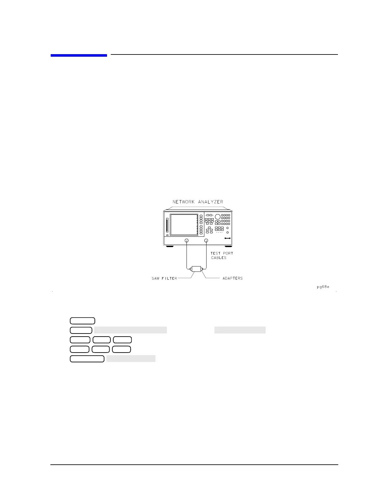
1. Connect the device as shown in Figure 3-2.
Figure 3-2 Device Connections for Time Domain Transmission Example Measurement
2. To choose the measurement parameters, press:
or on ET models:
3. Substitute a thru for the device under test and perform a frequency response correction. Refer to Chapter
6 , “Calibrating for Increased Measurement Accuracy.”
4. Reconnect your device under test.

 Loading...


