2-14
Making Mixer Measurements
Conversion Loss Using the Frequency Offset Mode
Setting Measurement Parameters for the Power Meter Calibration
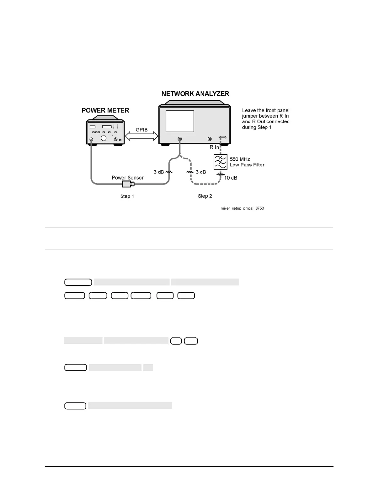
1. Connect the measurement equipment as shown in Step 1 of Figure 2-11.
Figure 2-11 Connections for R Channel and Source Calibration
CAUTION Note that the front panel jumper between R In and R Out must remain installed during the
procedure steps that use the connections in Step 1 of Figure 2-11.
2. From the front panel of the analyzer, set the desired receiver (RF) frequency and source output power by
pressing:
Note that these are the example RF start and stop frequencies. Enter the RF start and stop
frequencies for your measurement instead.
If the LO frequency is not set to 0 Hz, press:
3. To select the measurement trace, press:
The measurement trace is shown on the display.
4. Select the analyzer as the system controller: