1-58
Making Measurements
Measuring Amplifiers
Measuring Gain Compression
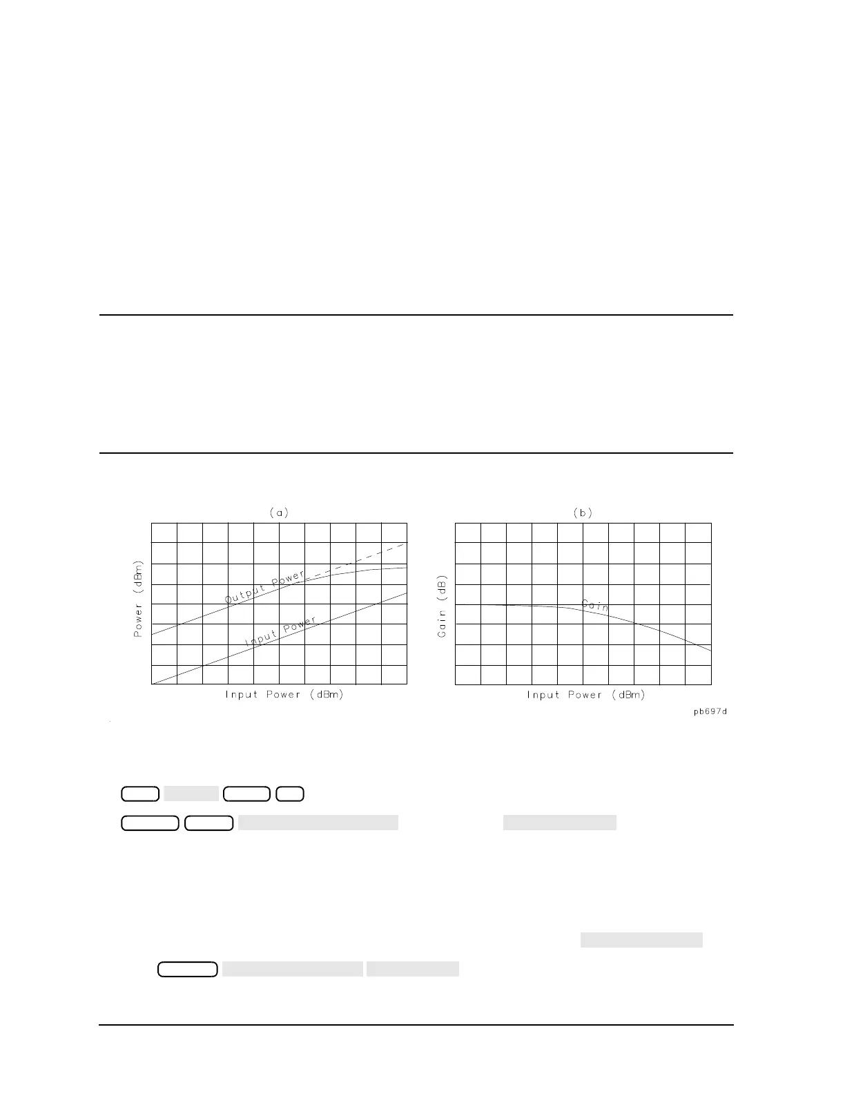
Gain compression occurs when the input power of an amplifier is increased to a level that reduces the gain
of the amplifier and causes a nonlinear increase in output power. The point at which the gain is reduced by 1
dB is called the 1 dB compression point. The gain compression will vary with frequency, so it is necessary to
find the worst-case point of gain compression in the frequency band.
Once that point is identified, you can perform a power sweep of that CW frequency to measure the input
power at which the 1 dB compression occurs and the absolute power out (in dBm) at compression. The
following steps provide detailed instruction on how to apply various features of the analyzer to accomplish
these measurements.
NOTE In a compression measurement it is necessary to know the RF input or output power at a
certain level of gain compression. Therefore, both gain and absolute power level need to be
accurately characterized. Uncertainty in a gain compression measurement is typically less
than 0.05 dB. Also, each input channel of the analyzer is calibrated to display absolute power
(typically within +0.5 dBm up to 3 GHz, and +1 dB up to 6 GHz). This can be improved by
calibrating the power meter. Refer to
"Power Meter Measurement Calibration" on page 6-33
for information on calibrating the power meter.
Figure 1-48 Diagram of Gain Compression
1. Set up the stimulus and response parameters for your amplifier under test. To reduce the effect of noise
on the trace, press:
or on ET models:
2. Perform the desired error correction procedure. Refer to Chapter 6 , "Calibrating for Increased
Measurement Accuracy" for instructions on how to make a measurement correction.
3. Connect the amplifier under test.
4. To produce a normalized trace that represents gain compression, perform either step 5 or step 6. (Step 5
uses trace math and step 6 uses uncoupled channels and the display function
.)
5. Press to produce a normalized trace.