3-36
Making Time Domain Measurements
Gating
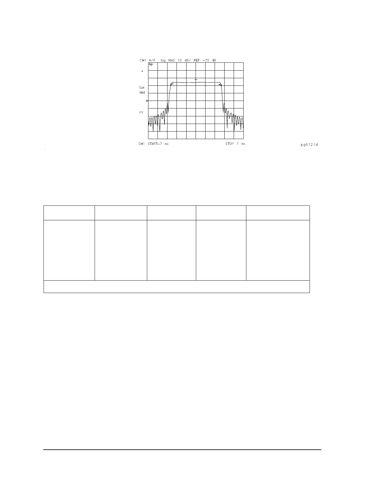
Figure 3-27 Gate Shape
Selecting Gate Shape
The four gate shapes available are listed in Tabl e 3- 4. Each gate has a different passband flatness, cutoff
rate, and sidelobe levels.
The passband ripple and sidelobe levels are descriptive of the gate shape. The cutoff time is the time
between the stop time (6 dB on the filter skirt) and the peak of the first sidelobe, and is equal on the left
and right side skirts of the filter. As shown in
Tabl e 3-4, the minimum gate span is just twice the cutoff time
because it has no passband. Always choose a gate span wider than the minimum. For most applications, do
not be concerned about the minimum gate span, simply use the knob to position the gate markers around
the desired portion of the time domain trace.
Tab le 3-4 Gate Characteristics
Gate Shape Passband Ripple Sidelobe Levels Cutoff Time Minimum Gate Span
Gate Span
Minimum 0.10 dB 48 dB 1.4/Freq Span 2.8/Freq Span
Normal 0.10 dB 68 dB 2.8/Freq Span 5.6/Freq Span
Wide 0.10 dB 57 dB 4.4/Freq Span 8.8/Freq Span
Maximum 0.10 dB 70 dB 12.7/Freq Span 25.4/Freq Span
Note: With 1601 frequency points, gating is available only in the bandpass mode.

 Loading...


