6-38
Calibrating for Increased Measurement Accuracy
Power Meter Measurement Calibration
Using Continuous Correction Mode
You can set the analyzer to update the correction table at each sweep (as in a leveling application), using the
continuous sample mode. When the analyzer is in this mode, it continuously checks power at every point in
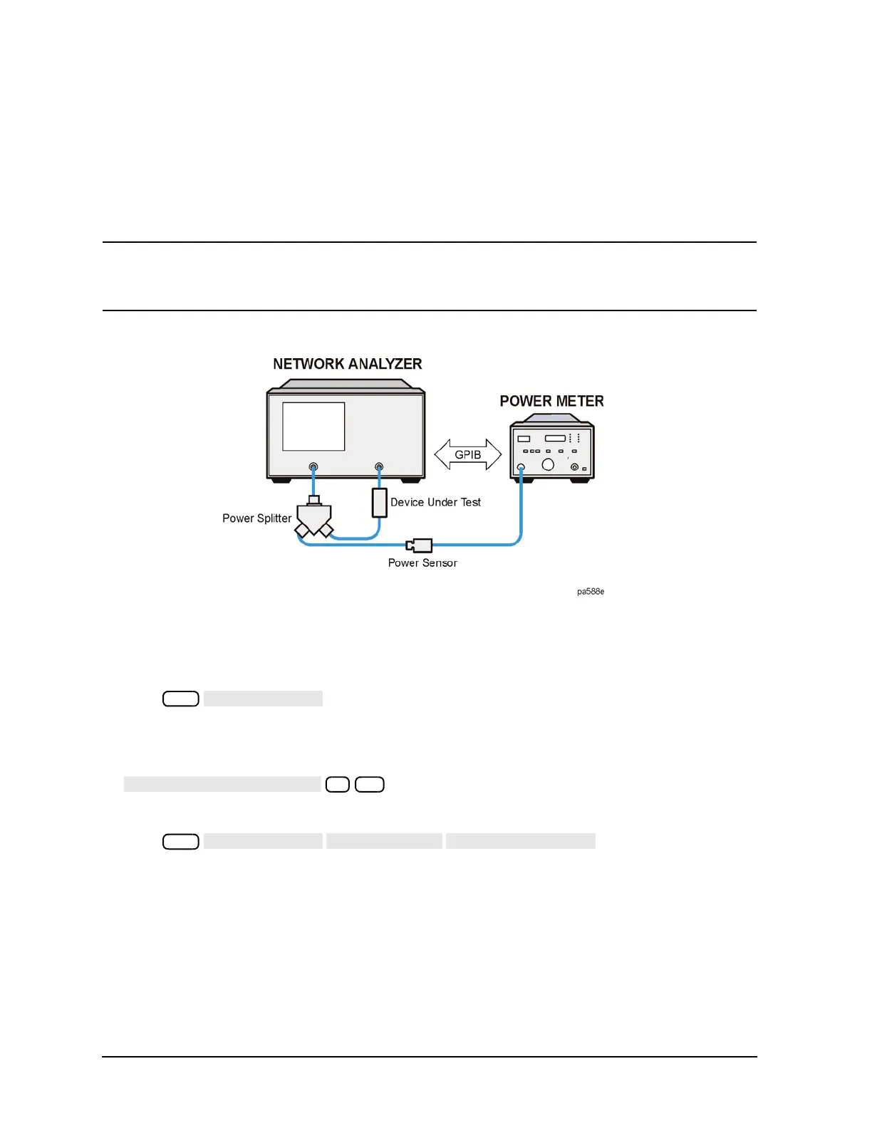
each sweep. You must keep the power meter connected as shown in
Figure 6-11. This mode is also known
as power meter leveling, and the speed is limited by the power meter.
NOTE You may level at the input of a device under test, using a 2-resistor power splitter or a
directional coupler before the device; or level at the output of the device using a 3-resistor
power splitter or a bidirectional coupler after the device.
Figure 6-11 Continuous Correction Mode for Power Meter Calibration
1. Connect a power splitter or directional coupler to the port supplying RF power to your test device, as
shown in
Figure 6-11.
2. Set test port power to approximate desired leveled power.
3. Press and enter the test port power level that you want the analyzer to
maintain at the input to your test device. Compensate for the power loss of the power splitter or
directional coupler in the setup.
4. If you want the analyzer to make more than one power measurement at each frequency data point, press
(where n = the number of desired iterations).
If you increase the number of readings, the power meter correction time will substantially increase.
5. Press to activate the power
meter correction.