1- 43
Making Measurements
Measuring Electrical Length and Phase Distortion
Measuring Electrical Length and Phase Distortion
Electrical Length
The analyzer mathematically implements a function similar to the mechanical “line stretchers” of earlier
analyzers. This feature simulates a variable length lossless transmission line, which you can add to or
remove from the analyzer's receiver input to compensate for interconnecting cables, etc. In this example,
the electronic line stretcher measures the electrical length of a SAW filter.
Phase Distortion
The analyzer allows you to measure the linearity of the phase shift through a device over a range of
frequencies and the analyzer can express it in two different ways:
• deviation from linear phase
•group delay
Measuring Electrical Length
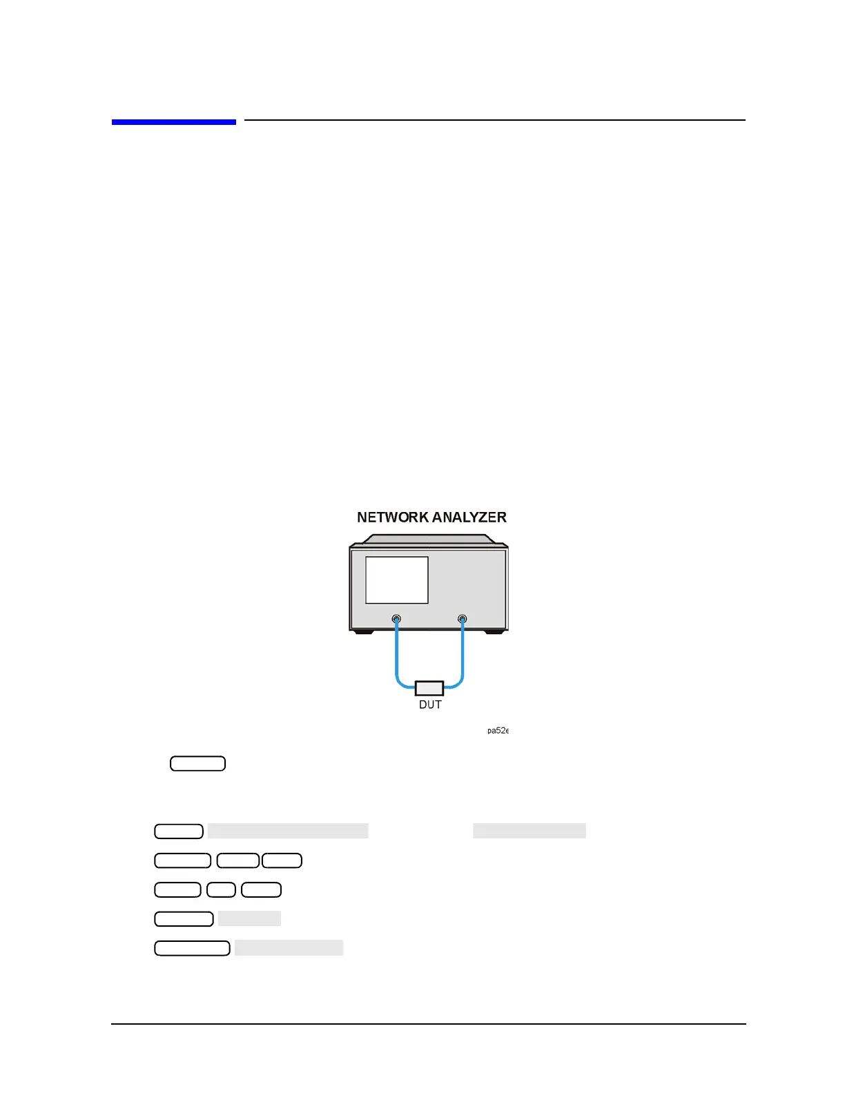
1. Connect your test device as shown in Figure 1-33.
Figure 1-33 Device Connections for Measuring Electrical Length
2. Press and choose the measurement settings. For this example, the measurement settings
include reducing the frequency span to eliminate under-sampled phase response. Press the following
keys as shown:
or on ET models:
You may also want to select settings for the number of data points, averaging, and IF bandwidth.