3- 9
Making Time Domain Measurements
Making Reflection Response Measurements
Making Reflection Response Measurements
The time domain response of a reflection measurement is often compared with the time domain
reflectometry (TDR) measurements. Like the TDR, the analyzer measures the size of the reflections versus
time (or distance). Unlike the TDR, the time domain capability of the analyzer allows you to choose the
frequency range over which you would like to make the measurement.
1. To choose the measurement parameters, press:
or on ET models:
2. Perform an S
11
1-port correction on PORT 1. Refer to Chapter 5 , "Optimizing Measurement Results" for a
detailed procedure.
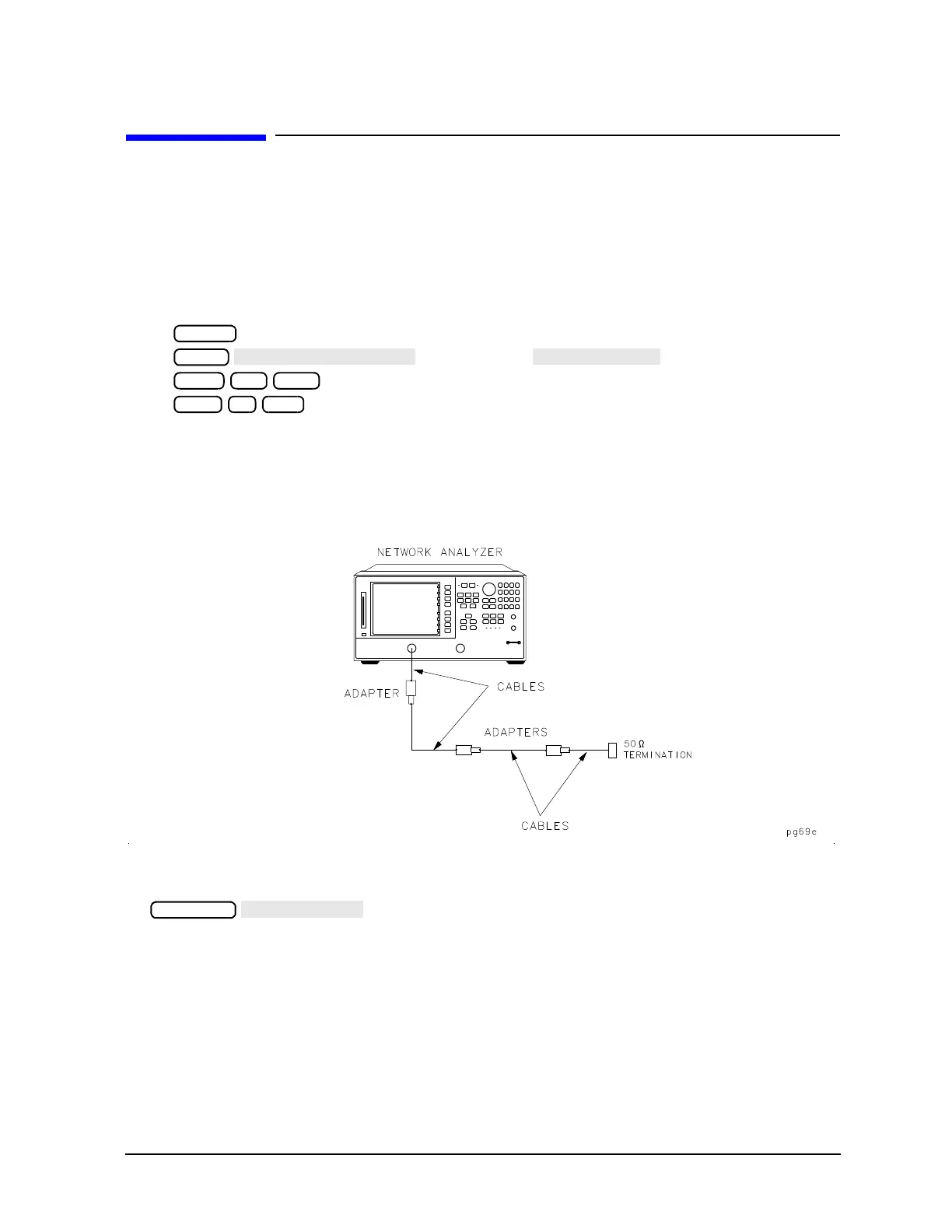
3. Connect your device under test as shown in Figure 3-7.
Figure 3-7 Device Connections for Reflection Time Domain Example Measurement
4. To better view the measurement trace, press:
Figure 3-8 shows the frequency domain reflection response of the cables under test. The complex ripple
pattern is caused by reflections from the adapters interacting with each other. By transforming this data
to the time domain, you can determine the magnitude of the reflections versus distance along the cable.

 Loading...


