3-18
Making Time Domain Measurements
Time Domain Low Pass Mode
Fault Location Measurements Using Low Pass
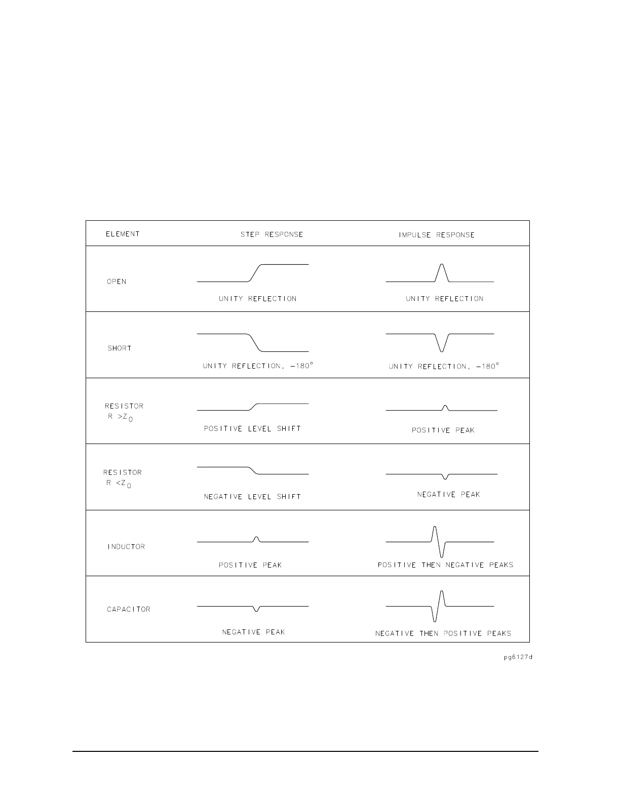
As described, the low pass mode can simulate the TDR response of the test device. This response contains
information useful in determining the type of discontinuity present.
Figure 3-13 illustrates the low pass responses of known discontinuities. Each circuit element was simulated
to show the corresponding low pass time domain S
11
response waveform. The low pass mode gives the test
device response either to a step or to an impulse stimulus. Mathematically, the low pass impulse stimulus is
the derivative of the step stimulus.
Figure 3-13 Simulated Low Pass Step and Impulse Response Waveforms (Real Format)
Figure 3-14 shows example cables with discontinuities (faults) using the low pass step mode with the real
format.

 Loading...


