Service Guide E8361-90001 5-13
PNA Series Microwave Network Analyzers Theory of Operation
E8361A Source Group Operation
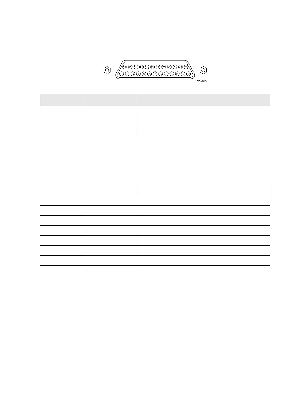
Table 5-3 TEST SET I/O Connector Pin Assignments
DB-25 Female Connector
Pin Numbers Name Function
1 SEL0 TTL out, test set select bit 0, tied to 0 V
2 Sweep Holdoff In TTL in, low level holds off sweep
3–6 AD12–AD8 TTL I/O, address and latched data
7 GND 0 V, ground reference
8 LAS TTL out, active low address strobe (1 µs min)
9–11 AD4–AD2 TTL I/O, address and latched data
12 GND 0 V, ground reference
13 Interrupt In TTL in, low level (10 µs min) aborts sweep
14 +22 V +22 Vdc, 100 mA max.
15–16 SEL1–2 TTL out, test set select bits 1-2, tied to 0 V
17 AD11 TTL I/O, address and latched data
18 SEL3 TTL out, test set select bit 3, tied to 0 V
19–21 AD7–5 TTL I/O, address and latched data
22–23 AD0–1 TTL I/O, address and latched data
24 LDS TTL out, active low data strobe (1 µs min)
25 RLW TTL out, high = read, low = write
 Loading...


