Home
Agilent Technologies
Measuring Instruments
PNA Series
Page 231
Agilent Technologies PNA Series - Page 231
327 pages
Manual
To Next Page
To Next Page
To Previous Page
To Previous Page
Loading...
Ser
vice G
uide
E836
1-90001
7-
19
PNA Series Microwa
ve
Network Analyzers
Repair and R
eplacement Procedures
E8361A
R
em
o
v
i
n
g
a
n
d
R
e
p
l
a
c
i
n
g
t
h
e
A
6
,
A
8
,
A
9
,
a
n
d
A
1
0
B
o
a
r
d
s
Fi
gu
re 7-
7
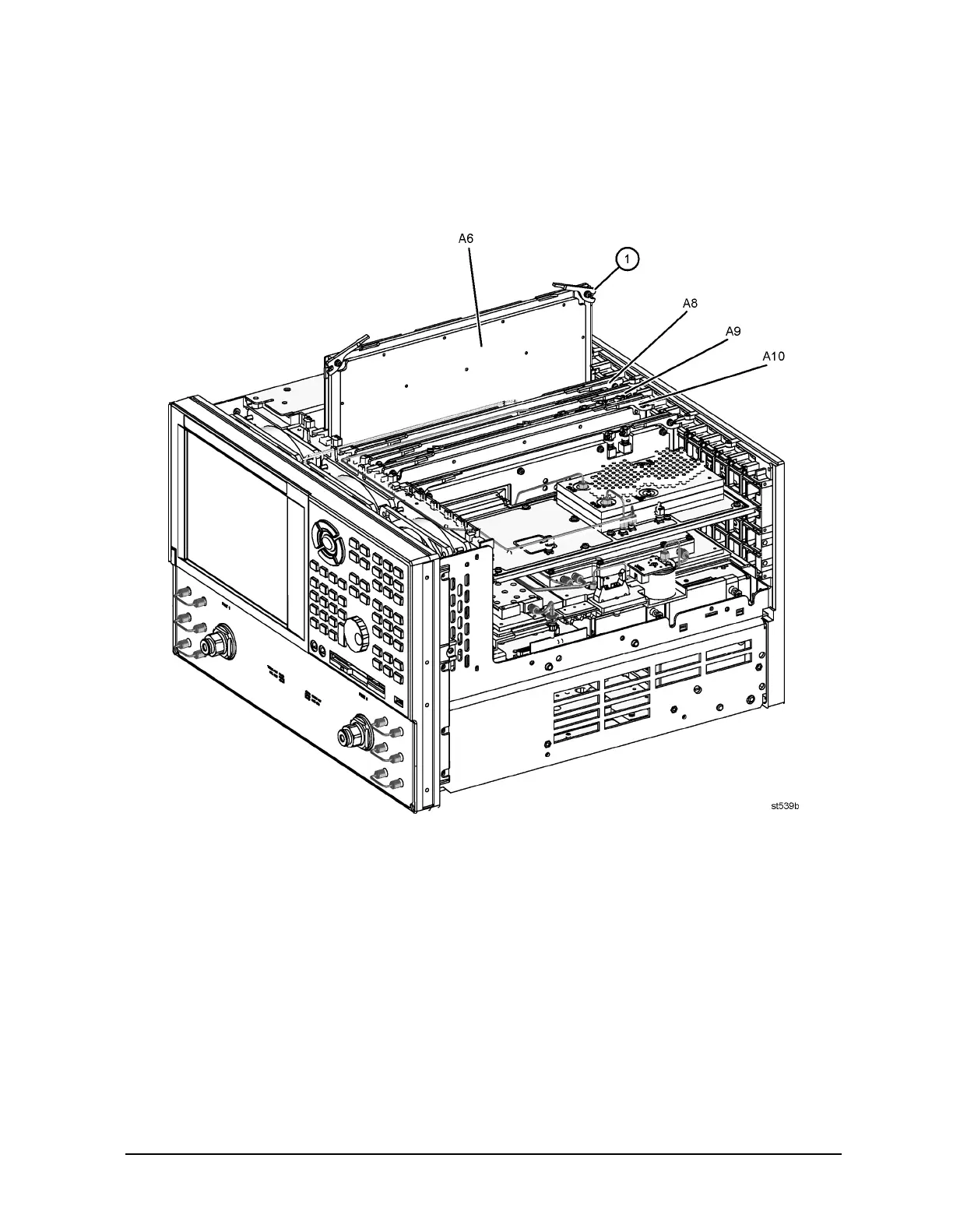
A6, A8, A9, and A10 Board Assemblie
s R
emoval
230
232
Table of Contents
Main Page
Default Chapter
3
Service Guide E8361-90001
3
Table of Contents
5
1 Safety and Regulatory Information
11
Information in this Chapter
12
Chapter One At-A-Glance
12
Safety Symbols
13
General Safety Considerations
13
Safety Earth Ground
13
Before Applying Power
13
Servicing
14
Electrostatic Discharge Protection
15
Regulatory Information
16
Instrument Markings
16
Lithium Battery Disposal
16
Compliance with Canadian EMC Requirements
17
Compliance with German FTZ Emissions Requirements
17
Compliance with German Noise Requirements
17
2 General Product Information
19
Information in this Chapter
20
Chapter Two At-A-Glance
20
Maintenance
21
Physical Maintenance
21
Electrical Maintenance
21
Analyzer Options, Upgrades, and Accessories
21
Option 010, Time Domain
21
Option 014, Configurable Test Set
21
Option 022, Extended Memory
22
Option 080, Frequency Offset Mode
22
Option 083, Frequency Converter Measurement Application
22
Option 099, Firmware Upgrade
22
CD-RW Drive
22
USB Hub
22
Option 0BW, Printed Service Guide
23
Option 1CP, Rack Mount Flange Kit for Instruments with Handles
23
Option 1CM, Rack Mount Flange Kit for Instruments Without Handles
23
Required Service Test Equipment
24
Agilent Support, Services, and Assistance
27
Contacting Agilent
27
Service and Support Options
28
Calibration Options
28
Shipping Your Analyzer to Agilent for Service or Repair
28
3 Tests and Adjustments
29
Information in this Chapter
30
Chapter Three At-A-Glance
30
Before You Begin
32
Verify the Operating Environment
32
Protect against Electrostatic Discharge (ESD)
32
Allow the Analyzer to Warm up
32
Review the Principles of Connector Care
33
About System Verification and Performance Tests
34
System Specifications
34
Instrument Specifications
34
System Verification Procedure
35
Performance Tests
35
Certificate of Calibration
35
ANSI/NCSL Z540-1-1994 Verification
36
Non-ANSI/NCSL Z540-1-1994 Verification
37
Preliminary Checks
38
The Operator's Check
38
The Test Port Cable Checks
40
System Verification
47
What the System Verification Verifies
47
Measurement Uncertainty
48
Measurement Traceability
49
Performing System Verification
50
Performance Tests (Agilent N2721A Software Package)
56
Source Power Accuracy Test
56
Source Power Linearity Test
57
Frequency Accuracy Test
57
Trace Noise Test
58
System Compression Test
58
Noise Floor Test
59
Calibration Coefficient Test
60
System Crosstalk Test
61
Dynamic Accuracy Test
62
Power Meter Accuracy Test
64
Adjustments
69
Source Calibration Adjustment
70
Receiver Calibration Adjustment
72
LO Power Adjustment
75
LO Offset Adjustment
76
10 Mhz Frequency Reference Adjustment
78
3.8 Ghz PMYO Frequency Adjustment
79
4 Troubleshooting
81
Information in this Chapter
82
Chapter Four At-A-Glance
82
Protect against Electrostatic Discharge (ESD)
83
Assembly Replacement Sequence
83
Getting Started with Troubleshooting
84
Check the Basics
84
Troubleshooting Organization
85
Power up Troubleshooting
86
Power Supply Check
87
Troubleshooting LCD Display Problems
93
Front Panel Troubleshooting
97
A1 Front Panel Keypad and RPG Test
97
A2 Display Test
99
A3 Front Panel Interface Board
100
Rear Panel Troubleshooting
101
Checking the USB Ports
101
Checking the SERIAL (RS-232), PARALLEL (1284-C), or VGA Port
102
Checking the GPIB Port
103
LAN Troubleshooting
104
Measurement System Troubleshooting
108
Verifying the A, B, R1, and R2 Traces (Standard S-Parameter Mode)
110
Where to Begin Troubleshooting
111
Checking the Source Group
115
Checking the Signal Separation Group
129
Checking the Receiver Group
132
Checking the Frequency Offset Group (Option 080)
134
Instrument Block Diagrams Sheet 1
140
Instrument Block Diagrams Sheet 2
142
5 Theory of Operation
143
Information in this Chapter
144
Chapter Five At-A-Glance
144
Network Analyzer System Operation
145
Functional Groups of the Network Analyzer
145
Source Group Operation
148
Band Modes
148
A8 Fractional-N Synthesizer Board
150
A17 L.O. Multiplier/Amplifier 12 (LOMA 12)
151
A18 Multiplier/Amplifier 24 (MA 24)
151
A19 Splitter
151
A20 L.O. Distribution Assembly (LODA)
151
A10 Frequency Reference Board
151
A11 Phase Lock Board
152
A21 Source Multiplier/Amplifier 50 (SOMA 50)
153
A16 Test Set Motherboard
154
Signal Separation Group Operation
158
A22 Switch
159
A23 and A24 Source Multiplier/Amplifier 70 (SOMA 70)
159
A25 and A26 Test Port Couplers
159
Option 014 Configurable Test Set
159
Receiver Group Operation
162
A27, A28, A29, and A30 Receiver First Converters (Mixers)
162
LO Reject/Filter Board
162
A31, A32, A33, and A34 Receiver Modules
162
A6 SPAM Board (Analog Description)
164
A35 Receiver Motherboard
164
Frequency Offset Group Operation (Option 080)
165
A9 Fractional-N Synthesizer Board
165
A13 Frequency Offset Receiver Assembly
165
Digital Processing and Digital Control Group Operation
166
Front Panel Subgroup
168
Data Acquisition and Processing Subgroup
169
Power Supply Group Operation
171
6 Replaceable Parts
173
Information in this Chapter
174
Chapter Six At-A-Glance
174
Ordering Information
175
Assembly Replacement Sequence
176
Rebuilt-Exchange Assemblies
177
Replaceable Parts Listings
178
Front Panel Assembly, All Options
182
Top Assemblies and Hardware, All Options Except 080
184
Top Assemblies and Hardware, All Options Including 080
186
Top Cables, All Options Except 080
188
Top Cables, All Options Including 080
190
Bottom Assemblies, no Options
192
Bottom RF Cables, no Options
194
Bottom Flexible Cables, no Options
196
Bottom Ribbon Cables and Wrapped-Wire, no Options
198
Bottom Hardware, no Options
200
Parts Included with Option 014 (with or W/O Option 080)
202
Internal Hardware and Parts, All Options
204
External Hardware and Parts, All Options
206
Hard Disk Drive Assembly
208
Rear Panel Assembly, All Options
209
Miscellaneous Part Numbers
210
Service Tools
210
Documentation
210
Protective Caps for Connectors
210
GPIB Cables/Gpib Adapter
210
ESD Supplies
211
Upgrade Kits
211
Touch-Up Paint
211
USB Accessories
211
Miscellaneous Part Numbers (Continued)
212
Rack Mount Kits and Handle Kits
212
7 Repair and Replacement Procedures
213
Information in this Chapter
214
Chapter Seven At-A-Glance
214
Before Starting the Removal and Replacement Procedures
215
Personal Safety Warnings
215
Electrostatic Discharge (ESD) Protection
215
Assembly Replacement Sequence
215
Removal and Replacement Procedures
216
Removing the Covers
218
Raising and Removing the Receiver Deck
220
Removing and Replacing the Front Panel Assembly
222
Removing and Replacing Front Panel Subassemblies
224
Removing and Replacing the Display Inverter Board and the Display Lamp
226
Removing and Replacing the A4 Power Supply Assembly
228
Removing and Replacing the A6, A8, A9, and A10 Boards
230
Removing and Replacing the A11 Phase Lock Board
232
Removing and Replacing the A12 Source 20
234
Removing and Replacing the A13 Frequency Offset Receiver Assembly
236
Removing and Replacing the A14 System Motherboard
238
Removing and Replacing the A15 CPU Board
240
Removing and Replacing the A16 Test Set Motherboard
242
Removing and Replacing the A17 LOMA 12
244
Removing and Replacing the A18 MA 24
246
Removing and Replacing the A19 Splitter
248
Removing and Replacing the A20 LODA
250
Removing and Replacing the A21 SOMA 50
252
Removing and Replacing the A22 Switch
254
Removing and Replacing the A23 and A24 SOMA 70S
256
Removing and Replacing the A25 and A26 Test Port Couplers
258
Removing and Replacing the A27, A28, A29, and A30 First Converters (Mixers) and Mixer Bias Board
260
Removing and Replacing the A31, A32, A33, and A34 Receiver Modules and lo Reject Filter Board
262
Removing and Replacing the A35 Receiver Motherboard
264
Removing and Replacing the A40 Floppy Disk Drive
266
Removing and Replacing the A41 Hard Disk Drive
268
Tools Required
269
Removing and Replacing the Midweb and the B1 Fan
274
Removing and Replacing the USB Hub
277
Post-Repair Procedures
278
A Error Terms
281
Information in this Appendix
282
Appendix A At-A-Glance
282
Using Error Terms as a Diagnostic Tool
283
Preventive Maintenance
283
Troubleshooting
283
Performing Measurement Calibration
284
Using Flowgraphs to Identify Error Terms
284
Accessing Error Terms
286
Manual Access to Error Terms
286
Programmatic Access to Error Terms
287
Error Term Data
288
If Error Terms Seem Worse than Expected
288
Directivity (EDF and EDR
290
Source Match (ESF and ESR
291
Load Match (ELF and ELR
292
Reflection Tracking (ERF and ERR
293
Transmission Tracking (ETF and ETR
294
Isolation (EXF and EXR
295
B Option Enable Utility
297
Information in this Appendix
298
Appendix B At-A-Glance
298
Accessing the Option Enable Utility
299
Installing or Removing Options
299
Repairing and Recovering Option Data
300
Recovery of Data after Repair
300
Recovery of Data if Option or Model Numbers Are Incorrect
300
Installing or Changing a Serial Number
301
C Firmware Upgrades
303
Information in this Appendix
304
Appendix C At-A-Glance
304
Downloading from the Internet
304
How to Check the Current Firmware Version
304
Downloading Using Option 099, Firmware Upgrade
305
Installation Requirements
305
Downloading from a USB CD Drive Connected to the Analyzer
305
Downloading from a Shared CD Drive over the LAN
305
Downloading over the LAN
306
D Operating System Recovery
307
Information in this Appendix
308
Appendix D At-A-Glance
308
Overview
309
System Recovery Procedure
310
If the Operating System Does Not Boot from the Hard Disk Drive
311
If the Operating System Does Not Boot from the Floppy Disk Drive
312
Other manuals for Agilent Technologies PNA Series
Installation Note
24 pages
Installation And Quick Start Guide
32 pages
Related product manuals
Agilent Technologies PSA Series
434 pages
EPM-P Series
8 pages
Agilent Technologies 2100
366 pages
Agilent Technologies N6705
210 pages
Agilent Technologies 4349B
233 pages
Agilent Technologies 4288A
289 pages
Agilent Technologies 8163A
466 pages
Agilent Technologies 4294A
469 pages
Agilent Technologies 89410A
339 pages
Agilent Technologies N5230A
262 pages
Agilent Technologies 8753ES
479 pages
Agilent Technologies N1911A
297 pages