7Performance Tests
Agilent U1602B/U1604B User’s and Service Guide 137
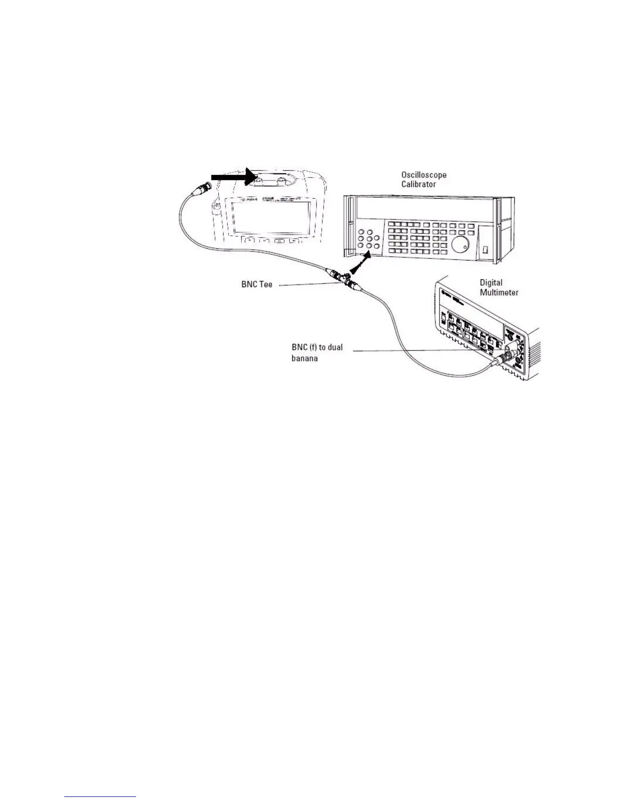
Figure 7-1 Test connection from calibrator to instrument and digital multimeter
4 Enable the Y- Cursor and align the Y1 cursor with the signal trace.
5 Adjust the output of the calibrator and observe the reading display on
the multimeter.
6 Wait a few seconds for the measurement to settle. Align the Y2 cursor
with the updated signal trace.
7 Compare the measurement results (Delta) displayed on the instrument
and multimeter to the corresponding test limits shown in Table 7- 3.
8 Continue to check voltage measurement accuracy with the remaining
Volts/div setting values in Table 7- 3.
9 When you have finished checking all of the power supply setting values,
disconnect the power supply from the oscilloscope.
10 Repeat the same verification procedures for channel 2.

 Loading...


