Using the Scope Functions 3
Agilent U1602B/U1604B User’s and Service Guide 31
Channel Coupling Control
The channel coupling control can be used to remove any DC offset voltage
on a waveform. You can select the input channel coupling to either AC
(alternating current), DC (direct current) or Gnd (Ground).
To select the input channel coupling, follow the procedures below:
1 Go to individual channel 1 and channel 2 menu by pressing the
button.
2 On page 1/2 of each respective channel’s submenu, you can view and
set the channel coupling by pressing the F2 softkey. A pull- up menu is
displayed with the selections of AC, DC and GND.
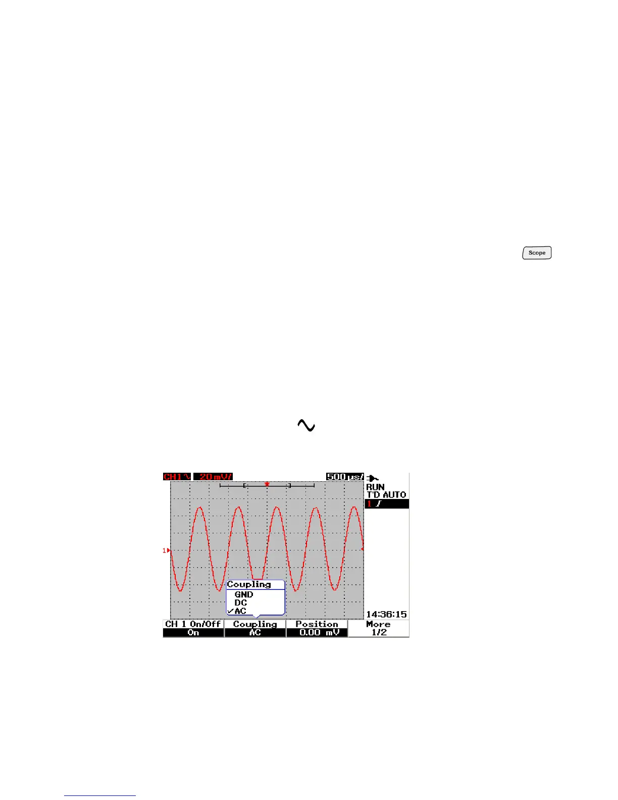
AC Channel Coupling
AC coupling is useful for viewing waveforms with large DC offsets. You
can select AC coupling to block any DC component from being passed
through the instrument. In this case, only AC component of the input
signal can be viewed. The symbol is shown at the top left of the status
line. See Figure 3- 6 for AC channel coupling.
Figure 3-6 AC channel coupling