Using the Digital Multimeter Functions 4
Agilent U1602B/U1604B User’s and Service Guide 103
Diode Test
To perform the diode test, do the following instructions:
1 Press button to access meter menu.
2 Press F2 to access ohmmeter submenu.
3 In the ohmmeter submenu, press F1 to select the diode test from the
pull- up menu.
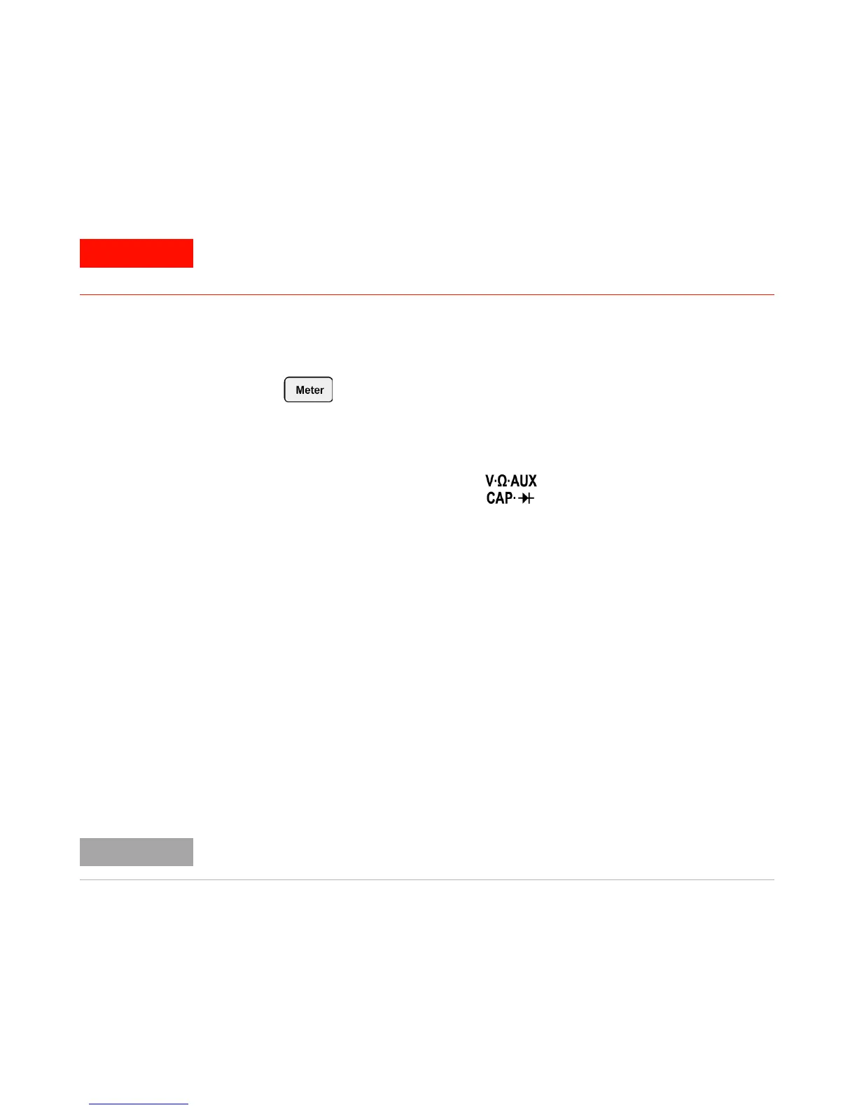
4 Connect the red test lead to the input terminal and the black
test lead to the COM terminal.
5 Probe the red test point to the positive terminal (anode) of the diode
and the black test lead on the negative terminal (cathode).
6 Read the voltage reading from the display.
7 Reverse the polarity of the probes and measure the voltage across the
diode again. Read the voltage reading from the display.
8 Diode test result can be described as the following:
• Diode is considered good if the instrument displays a voltage value
(approximately 0.25 V for germanium and 0.7 V for silicon) in
forward bias mode and displays “OL” in reverse bias mode.
• Diode is considered shorted if the instrument displays approximately
0 V in both forward and reverse bias modes.
• Diode is considered open if the instrument displays “OL” in both
forward and reverse bias modes.
Disconnect circuit power and discharge all high-voltage capacitors before
performing diode test to avoid electric shock and damage to the instrument.
The typical diode forward bias is in the range of 0.3 V to 1.00 V.