3 Using the Scope Functions
32 Agilent U1602B/U1604B User’s and Service Guide
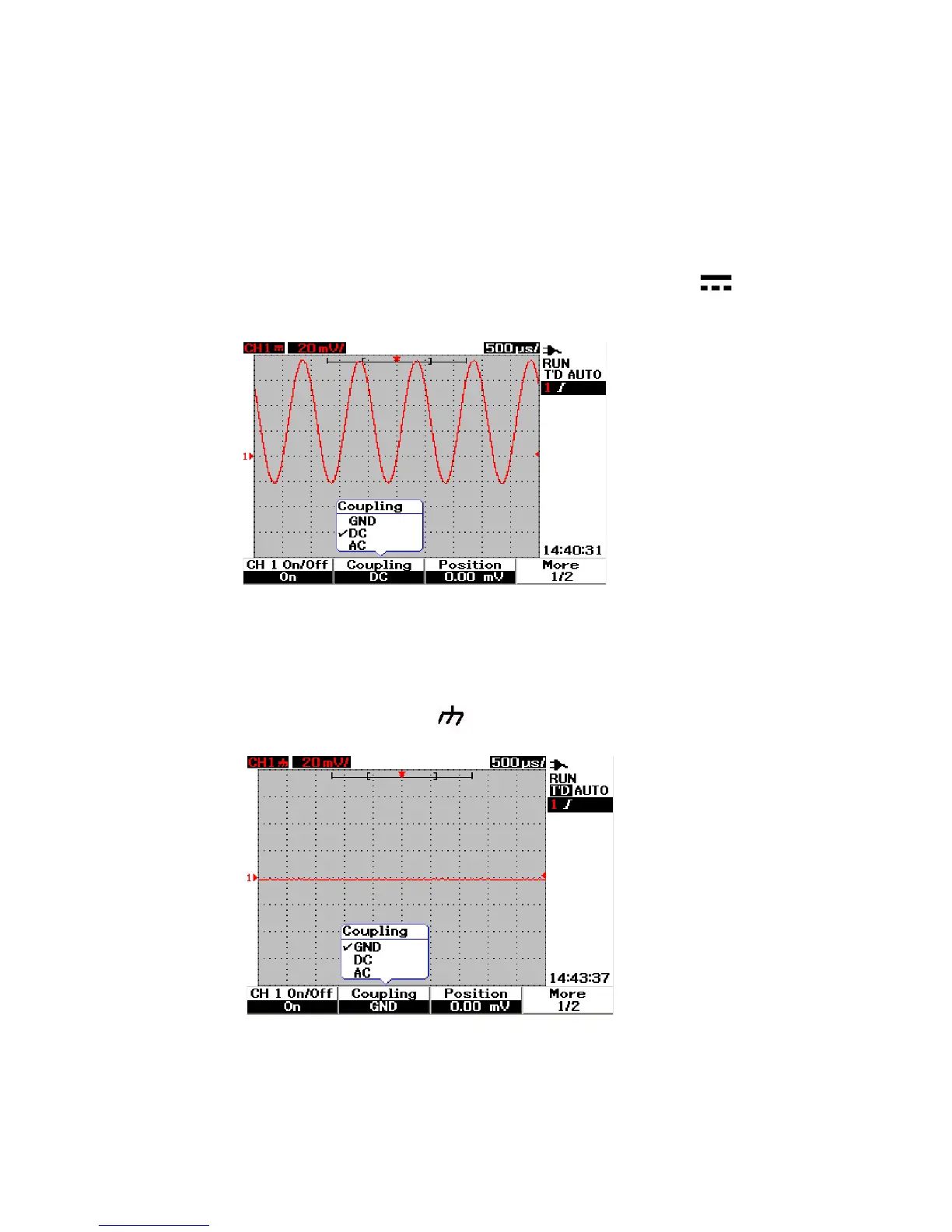
DC Channel Coupling
In DC coupling mode, both AC and DC components exist in the input
waveform to the instrument. DC coupling is useful for viewing waveforms
as low as 0 Hz that do not have large DC offsets. The symbol is
shown at the top left of the status line. See Figure 3- 7 for DC channel
coupling.
Figure 3-7 DC channel coupling
Ground channel coupling
In GND coupling mode, the waveform is disconnected from the
oscilloscope input. The symbol is shown at the top left of the status
line.See Figure 3- 8 for Gnd channel coupling.
Figure 3-8 Gnd channel coupling