MPLS Transport Profile (MPLS-TP)
Page 36 7210 SAS M, T, X, R6, Mxp MPLS Configura-
tion Guide
The MPLS-TP Tunnel ID and LSP ID are not to be confused with the RSVP-TE tunnel id
implemented on the 7210 system. Table 3 shows how these map to the X and Y ends of the tunnel
shown in the above figure for the case of co-routed bidirectional LSPs.
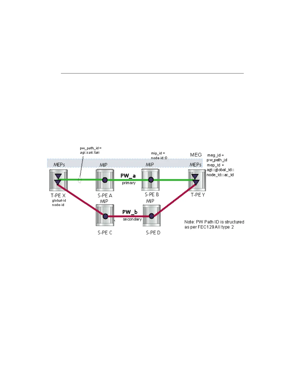
Figure 11: MPLS-TP PW Information Model
In the PW information model shown in Figure 11, the MS-PW is identified by the PW Path ID that
is composed of the full AGI:SAII:TAII. The PW Path ID is also the MEP ID at the T-PEs, so a user
does not have to explicitly configure a MEP ID; it is automatically derived by the system. For
MPLS-TP PWs with static labels, although the PW is not signaled end-to-end, the directionality of
the SAII and TAII is taken to be the same as for the equivalent label mapping message that is, from
downstream to upstream. This is to maintain consistency with signaled pseudowires using FEC
129.
On the 7210 SAS, an S-PE for an MS-PW with static labels is configured as a pair of spoke-sdps
bound together in an VLL service using the vc-switching command. Therefore, the PW Path ID
configured at the spoke-sdp level at an S-PE must contain the Global-ID, Node-ID and AC-ID at
Table 3: Mapping from RSVP-TE to MPLS-TP Maintenance Identifiers
RSVP-TE Identi-
fier
MPLS-TP Maintenance Identifier
Tunnel Endpoint
Address
Node ID (Y)
Tunnel ID (X) Tunnel Num (X)
Extended Tunnel ID Node ID (X)
Tunnel Sender
Address
Node ID (X)
LSP ID LSP Num