134 Rockwell Automation Publication 1769-UM011H-EN-P - April 2012
Appendix A Status Indicators
ControlNet Indicators
The ControlNet indicators are only on the 1769-L32C and 1769-
L35CR controllers.
Use these indicators to determine how your CompactLogix 1769-L32C or 1769-
L35CR controller is operating on the ControlNet network:
• Module Status
• Network Status
These indicators provide information about the controller and network when the
controller is connected to ControlNet via the BNC connectors.
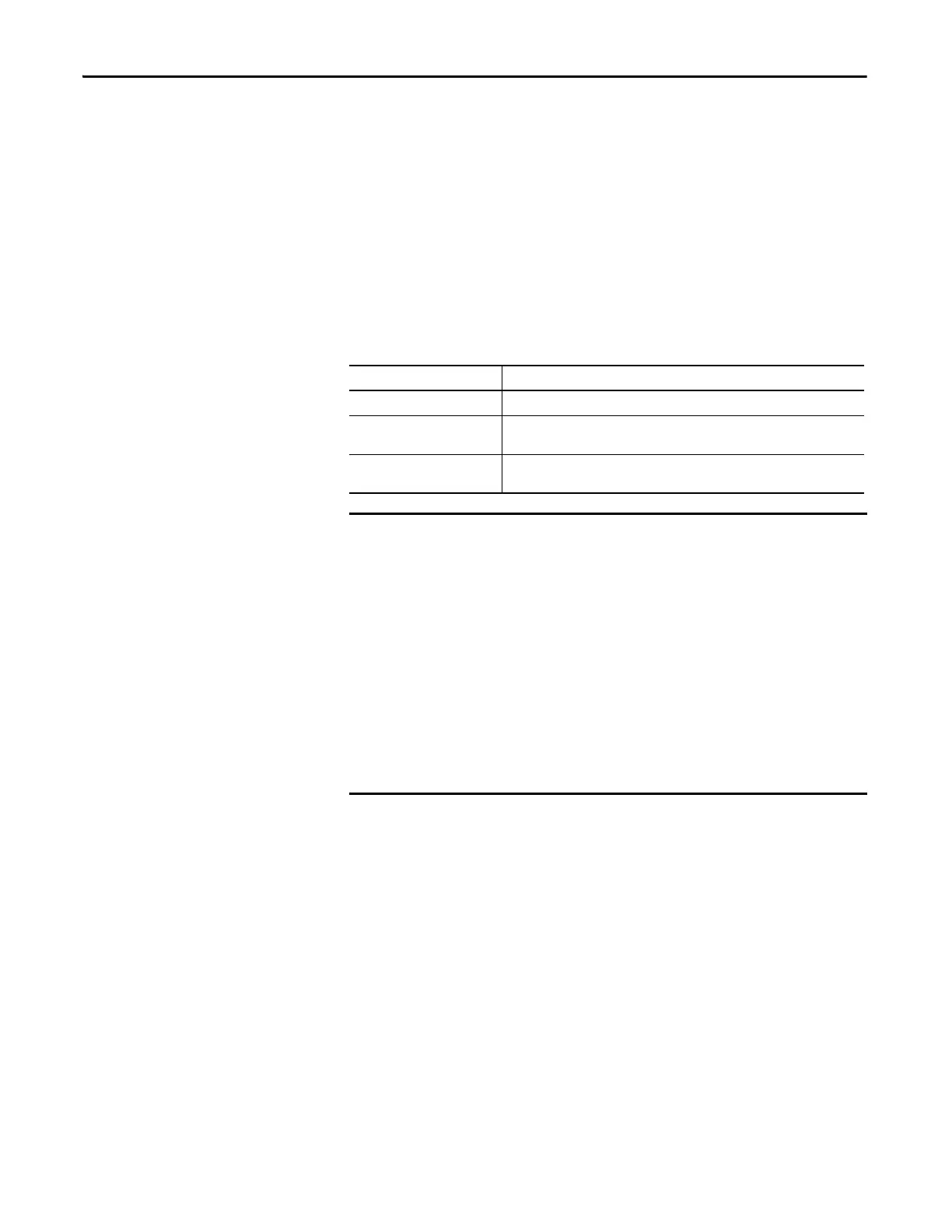
Table 34 - ControlNet Network Status Indicator States
Status Indicator State Interpretation
Steady The indicator is on continuously in the defined state.
Alternating When viewed together, two indicators alternate between two defined states; the
two indicators are always in opposite states, out of phase.
Flashing When viewed independent of another, an indicator alternates between the two
defined states; if both indicators are flashing, they flash together, in phase.
Keep in mind that the Module Status indicator reflects the module state (for
example, self-test, firmware update, normal operation but no connection
established). The network status indicators, A and B, reflect network status.
Remember that the host is able to engage in local messaging with the card
although it is detached from the network. Therefore, the Module Status
indicator is flashing green if the host has successfully started the card. Note,
however, that until the host removes reset, all communication port status
indicators.
When you view the indicators, always view the Module Status indicator first
to determine the state of the communication port. This information may
help you to interpret the network indicators. As a general practice, view all
indicators (Module Status and Network Status) together to gain a full
understanding of the daughtercard’s status.
 Loading...