26 Rockwell Automation Publication 1769-UM011H-EN-P - April 2012
Chapter 2 Install the 1769-L3x Controllers
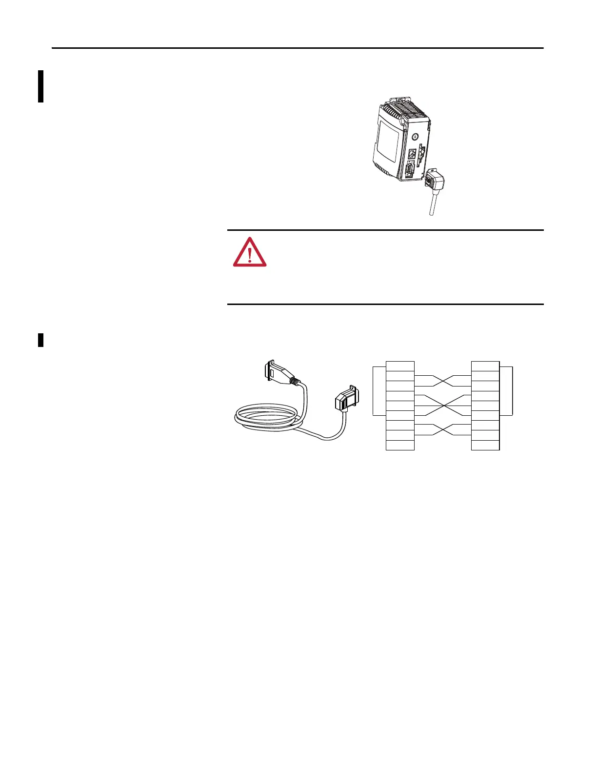
Make RS-232 Connections to
the Controller
Connect the 9-pin female end of the serial cable to the serial port of the
controller.
RS-232 Cable
WARNING: If you connect or disconnect the serial cable with power applied
to this module or the serial device on the other end of the cable, an electrical
arc can occur. This could cause an explosion in hazardous location
installations.
Be sure that power is removed or the area is nonhazardous before proceeding.
2 RDX
3 TXD
4 DTR
COMMON
6 DSR
7 RTS
8 CTS
9
1 CD
2 RDX
3 TXD
4 DTR
COMMON
6 DSR
7 RTS
8 CTS
9
1 CD
1747-CP3 or 1756-CP3
9-pin, Male D-shell
Straight Cable End
9-pin, Female D-shell
Right-angle Cable End
Straight Cable End Right-angle Cable End
This cable must be shielded and tied to the connector housing.
 Loading...