24 Rockwell Automation Publication 1769-UM011H-EN-P - April 2012
Chapter 2 Install the 1769-L3x Controllers
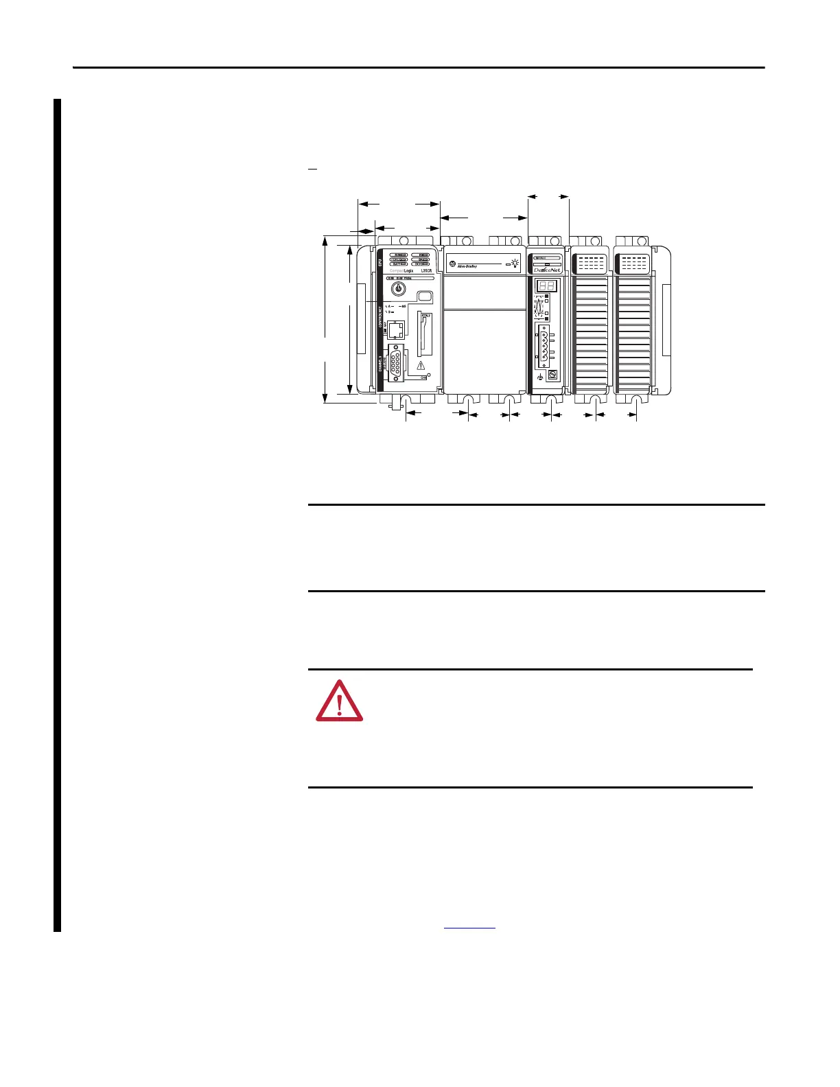
Dimensions
The figure shows dimensions in mm (in.). Hole spacing tolerance is
+
4 mm (0.016 in.).
Ground the Wiring
This product is intended to be mounted to a well-grounded mounting surface
such as a metal panel. Additional grounding connections from the controller’s
mounting tabs or DIN rail (if used) are not required unless the mounting surface
cannot be grounded.
Refer to Allen-Bradley Industrial Automation Wiring and Grounding
Guidelines, publication 1770-4.1
, for additional information.
Compact I/O expansion cables have the same dimensions as the end caps.
Expansion cables can be used on either the right or left end.
A 1769-ECR right end cap or 1769-ECL left end cap terminates the end of the
communication bus.
ATTENTION: This product is grounded through the DIN rail to chassis ground.
Use zinc-plated yellow-chromate steel DIN rail to assure proper grounding.
The use of other DIN rail materials (such as aluminum or plastic) that can
corrode, oxidize, or are poor conductors, can result in improper or
intermittent grounding. Secure DIN rail to mounting surface approximately
every 200 mm (7.8 in.) and use end-anchors appropriately.
31502-M
67.5
(2.68)
52.5
(2.06)
70
(2.76)
15
(0.59)
35
(1.38)
35
(1.38)
35
(1.38)
35
(1.38)
35
(1.38)
52.5
(2.06)
118
(4.65)
132
(5.20)
 Loading...