86 Rockwell Automation Publication 1769-UM011H-EN-P - April 2012
Chapter 6 Place, Configure, and Monitor I/O
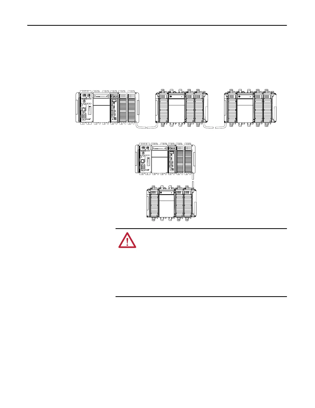
Place Local I/O Modules
Use the 1769-CRR1/-CRR3 or 1769-CRL1/-CRL3 expansion cable to connect
banks of I/O modules.
Each I/O module also has a power supply distance rating, the number of modules
from the power supply. The distance rating is printed on each module’s label.
Each module must be located within its distance rating.
Table 22 - Controller I/O Placement
The CompactLogix controller also supports distributed (remote) I/O via
these networks:
• EtherNet/IP
• ControlNet
• DeviceNet
1769-CRLx Cable
Horizontal
Orientation
Vertical Orientation
Bank 1 Bank 2
Bank 1
Bank 2
Bank 3
1769-CRLx Cable
1769-CRRx Cable
ATTENTION: The CompactLogix system does not support Removal and
Insertion Under Power (RIUP). While the CompactLogix system is under
power:
• any break in the connection between the power supply and the
controller (for example, removing the power supply, controller, or an I/O
module) may subject the logic circuitry to transient conditions above
the normal design thresholds and may result in damage to system
components or unexpected behavior.
• removing an end cap or an I/O module faults the controller and may
also result in damage to system components.
 Loading...