Rockwell Automation Publication 1769-UM011H-EN-P - April 2012 23
Install the 1769-L3x Controllers Chapter 2
6. Move the module’s bus lever fully to the left (D) until it clicks, being sure it
is locked firmly in place.
7. Attach an end-cap terminator (E) to the last module in the system by using
the tongue-and-groove slots as before.
8. Lock the end-cap bus terminator (F).
Mount the System
Minimum Spacing
Maintain spacing from enclosure walls, wireways, and adjacent equipment. Allow
50 mm (2 in.) of space on all sides, as shown. This provides ventilation and
electrical isolation.
ATTENTION: When attaching the controller, power supply, and I/O modules,
make sure the bus connectors are securely locked together to be sure of
proper electrical connection.
This equipment is not resistant to sunlight or other sources of UV radiation.
ATTENTION: During panel or DIN-rail mounting of all devices, be sure that all
debris (such as metal chips or wire strands) is kept from falling into the
controller. Debris that falls into the controller could cause damage while the
controller is energized.
Bottom
Side
Side
Top
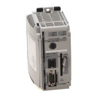
CompactLogix
Controller
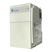
Power Supply
Compact I/O Module
End Cap
50 mm
(2 in.)
50 mm
(2 in.)
50
mm
(2 in
.)
50 mm
(2 in.)
Compact I/O Module
 Loading...