Rockwell Automation Publication 1769-UM011H-EN-P - April 2012 27
Install the 1769-L3x Controllers Chapter 2
Optical Isolator (1769-L31 only)
Channel 0 is fully isolated and does not need a separate isolation device.
Channel 1 is nonisolated. If you connect channel 1 to a device outside of the
system’s enclosure, consider installing an isolator (such as the 1761-NET-AIC
interface converter) between the controller and device..
Select the appropriate cable.
Default Serial Configuration
Channel 0 (serial port) has the following default communication configuration.
Port 1: DB-9
RS-232, DTE
Communication
Rate Selector
Switch
Port 2: Mini-DIN 8
RS-232
DC Power Source
Selector Switch
Terminals for External 24V DC
Power Supply
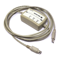
Isolator Use Cable
No The 1756-CP3 cable attaches the controller directly to the controller.
If you make your own cable, it must be shielded and the shields must be tied to the metal shell surrounding the pins on the ends
of the cable.
You can also use a 1747-CP3 cable. This cable has a taller right-angle connector housing than the 1756-CP3 cable.
Yes The 1761-CBL-AP00 cable (right-angle connector to controller) or the 1761-CBL-PM02 cable (straight connector to the controller)
attaches the controller to port 2 on the 1761-NET-AIC isolator. The mini-DIN connector is not commercially available, so you
cannot make this cable.
DB-9 Right-angle or
Straight Cable End
8-pin, Mini-DIN
Cable End
Pin DB-9 End Mini-DIN End
1DCD DCD
2 RxD RxD
3TxD TxD
4DTR DTR
5 Ground Ground
6DSR DSR
7RTS RTS
8CTS CTS
9N/A N/A
12
3
4
678
6
7
8
9
1
2
3
4
5
Parameter Default
Protocol DF1 full-duplex
Communication Rate 19.2 Kbps
Parity None
Station Address 0
Control Lines No Handshaking
 Loading...