EasyManuals Logo

Allen-Bradley CompactLogix Series User Manual

Allen-Bradley CompactLogix Series
218 pages
To Next Page IconTo Next Page
To Previous Page IconTo Previous Page
Page #20 background imageLoading...
Page #20 background image
20 Publication IASIMP-QS001C-EN-P - October 2009
Chapter 1 Prepare the CompactLogix Hardware
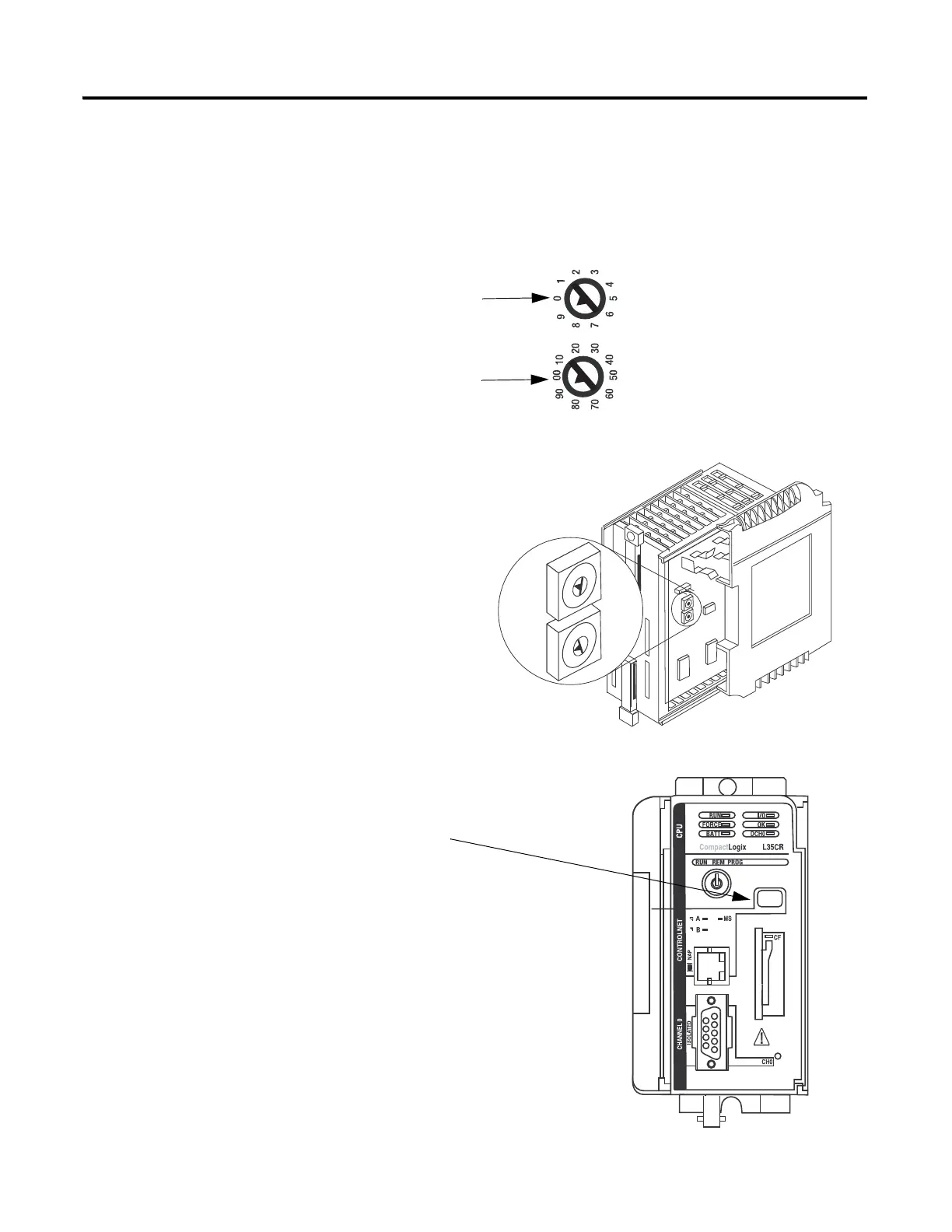
Set the ControlNet Node Address
1769-L32C or 1769-L35CR controllers
00
90
70
80
60
50
40
30
20
10
0
9
7
8
6
5
4
3
2
1
Tens
Digit
Ones
Digit
1. Use a small, flathead screwdriver to set the
node address to node 01.
2. Record the node address on the front panel
overlay.
Controllers are shipped with
the node address set at 99.
01 Shown
ControlNet Node Address Switches
Ones
Tens
Ones
Tens

Table of Contents

Questions and Answers:

Question and Answer IconNeed help?

Do you have a question about the Allen-Bradley CompactLogix Series and is the answer not in the manual?

Allen-Bradley CompactLogix Series Specifications

General IconGeneral
Communication PortsEtherNet/IP
Programming SoftwareStudio 5000 Logix Designer
Power Supply24V DC
SeriesCompactLogix
Programming LanguagesLadder Diagram (LD), Structured Text (ST), Function Block Diagram (FBD), Sequential Function Chart (SFC)
Operating Temperature0°C to 60°C (32°F to 140°F)
MountingDIN rail
Processor TypeVarious (depends on model)

Related product manuals