Publication IASIMP-QS001C-EN-P - October 2009 57
Prepare the PowerFlex 70 Drive Chapter 4
Mount the PowerFlex 70 Drive
For the purpose of this quick start, the PowerFlex 70 drive can be propped in a safe and
convenient location.
For mounting instructions, see the PowerFlex 70 Drive User Manual, publication
20A-UM001
.
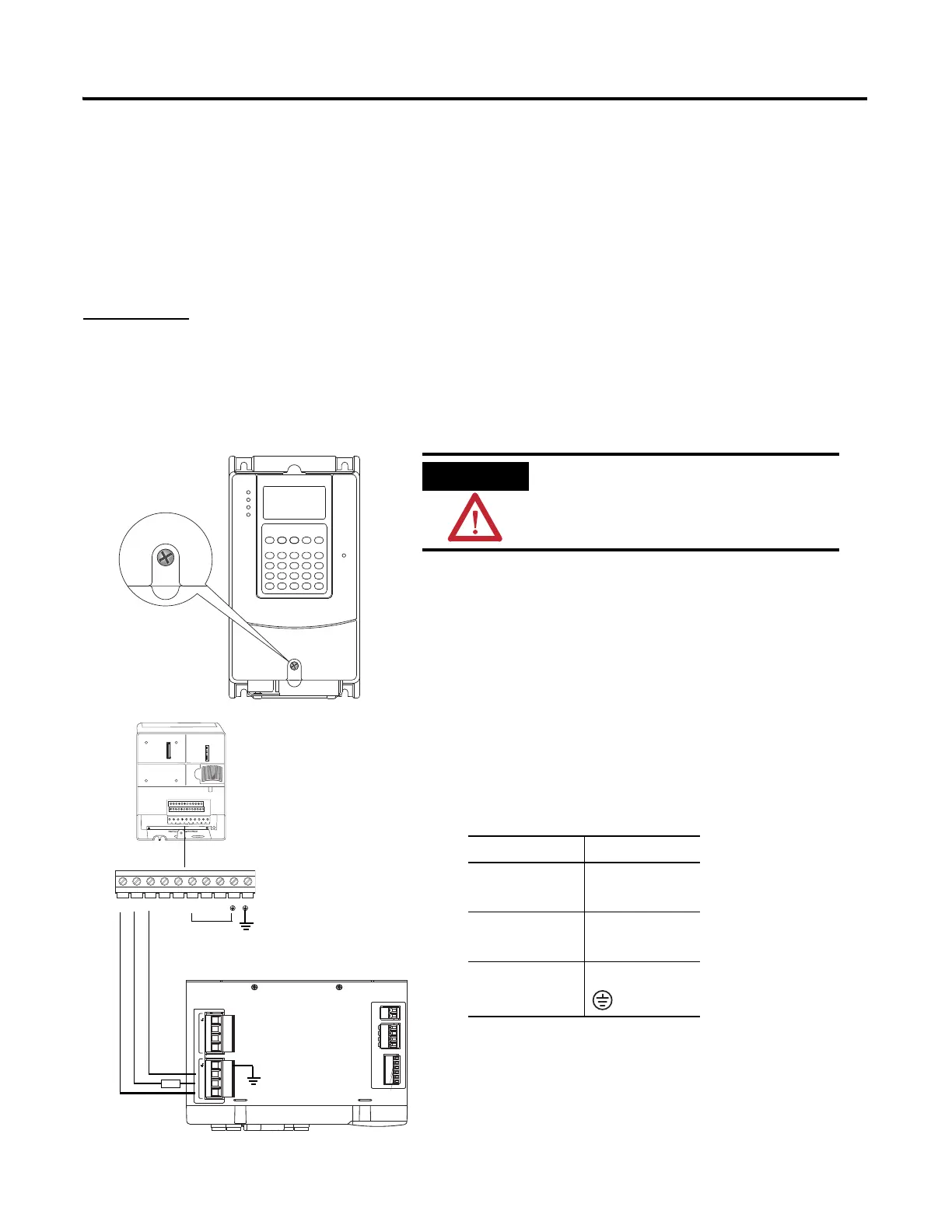
Wire Power
1. Loosen the screw and remove the cover.
2. Loosen the screws and slide the metal plate out
of the drive.
3. Connect the 120/240V AC, V AC COM and
chassis ground wires to the terminal block.
4. Replace the metal plate and tighten the screws.
Connect To
120/240V AC
L1
R
V AC COM
L2
S
Chassis ground
PE
Verify that all incoming power is
turned off before wiring power.
L1
R
L2
S
L3
T
BR1
+DC
BR2
BRK
T1
U
T2
V
T3
W
PE PE
195-265 VAC LINE, 50/60 Hz
L3
L2
L1
230 VAC SUPPLY
CTRL2
CTRL1
195-265 VAC LOAD, 50/60 Hz
L3'
L2'
L1'
CONTROL VAC
AUX2
AUX2
AUX1
AUX1
I/O_COM
I/O_PWR
I/O_COM
I/O_PWR
I/O_COM
I/O_PWR
24 VDC SUPPLY
1 2
1 2 3 4
1 2 3 4
1 2 3 4
1 2 3 4 5 6
AUX1
Optional LIM 240V
AC
3-Phase Load
Connector
Motor
fus
Top View

 Loading...


