EasyManuals Logo

Allen-Bradley CompactLogix Series User Manual

Allen-Bradley CompactLogix Series
218 pages
To Next Page IconTo Next Page
To Previous Page IconTo Previous Page
Page #74 background imageLoading...
Page #74 background image
74 Publication IASIMP-QS001C-EN-P - October 2009
Chapter 6 Prepare the PanelView Plus Terminal
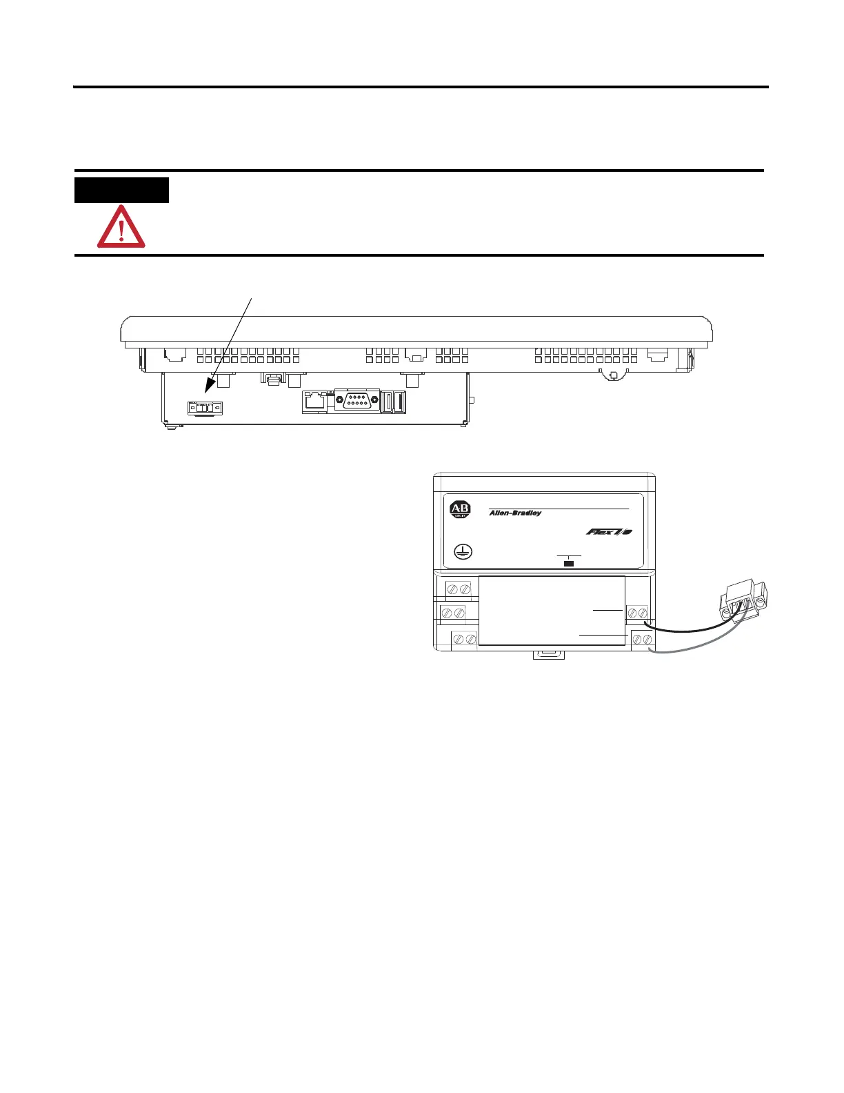
Wire the PanelView Plus Terminal to the Power Supply
rewoP
CD V42
YLPPUS REWOP
3SP-4971
V42
MOC
+
1. Remove the terminal block from the PanelView Plus terminal.
Verify that all incoming power is turned off before wiring power.
Common
Power
2. Connect the 12/24V DC common and
12/24V DC power wires from the power
supply to the terminal block,
- (common) and + (power).
3. Connect the terminal block to the
PanelView Plus.
4. Turn on incoming power.

Table of Contents

Questions and Answers:

Question and Answer IconNeed help?

Do you have a question about the Allen-Bradley CompactLogix Series and is the answer not in the manual?

Allen-Bradley CompactLogix Series Specifications

General IconGeneral
Communication PortsEtherNet/IP
Programming SoftwareStudio 5000 Logix Designer
Power Supply24V DC
SeriesCompactLogix
Programming LanguagesLadder Diagram (LD), Structured Text (ST), Function Block Diagram (FBD), Sequential Function Chart (SFC)
Operating Temperature0°C to 60°C (32°F to 140°F)
MountingDIN rail
Processor TypeVarious (depends on model)

Related product manuals