EasyManuals Logo

Allen-Bradley PowerFlex 40 User Manual

Allen-Bradley PowerFlex 40
218 pages
To Next Page IconTo Next Page
To Previous Page IconTo Previous Page
Page #132 background imageLoading...
Page #132 background image
132 Publication IASIMP-QS001C-EN-P - October 2009
Chapter 11 Add Distributed I/O Modules to the Project
Node Number
Slot Number
Tag Type
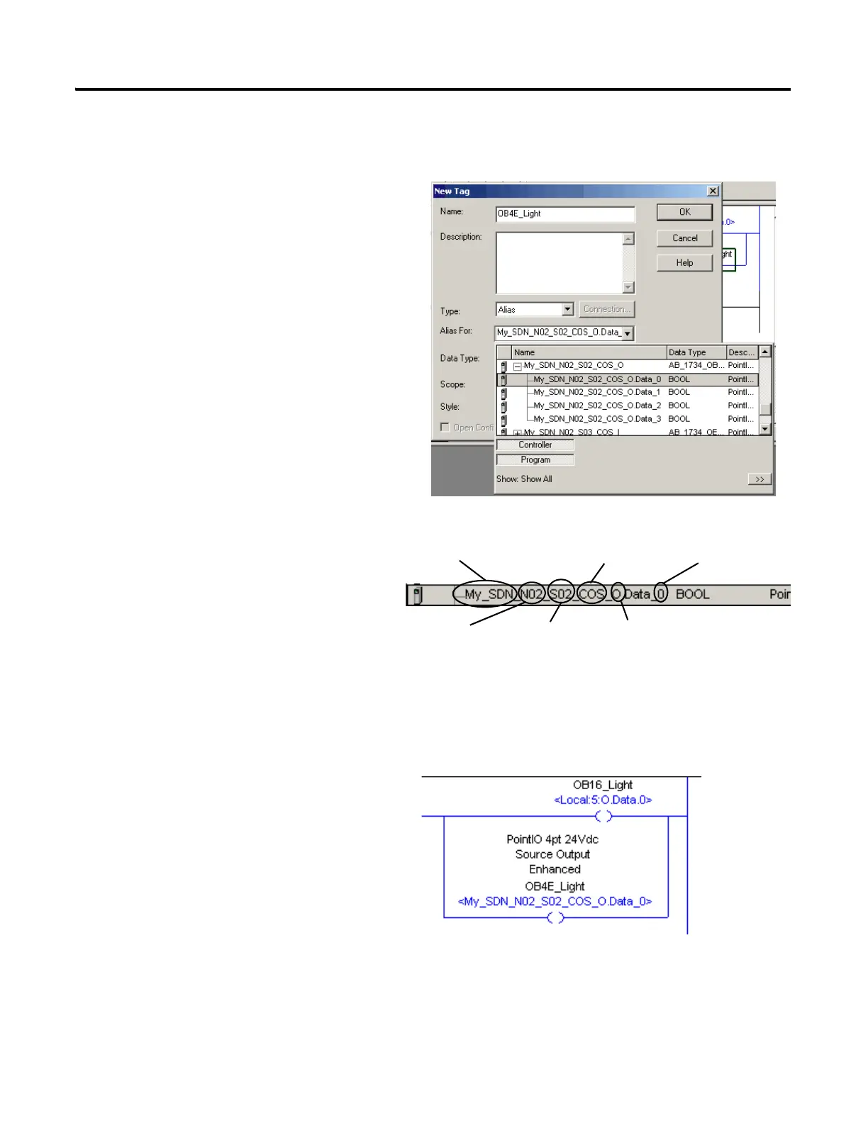
18. From the Type pull-down menu,
choose Alias.
19. From the Alias For pull-down menu,
browse to find SDN output data tags.
20. Select the output data tag that
corresponds to the LED indicator you
want to turn on.
Use this diagram as a reference when
selecting your output tag.
For example, selecting
the tag that ends with
O.Data.0 will turn on light 0 of
the output module.
21. Click OK.
Connection Type
SDN Module Name
Channel

Table of Contents

Other manuals for Allen-Bradley PowerFlex 40

Questions and Answers:

Question and Answer IconNeed help?

Do you have a question about the Allen-Bradley PowerFlex 40 and is the answer not in the manual?

Allen-Bradley PowerFlex 40 Specifications

General IconGeneral
Output Voltage0 to Input Voltage
EnclosureIP20
Control MethodV/Hz, Sensorless Vector Control
CommunicationRS485
Frequency0 to 400 Hz
ProtectionOverload, Overvoltage, Undervoltage, Short Circuit
Operating Temperature-10 to 50°C (14 to 122°F)
Storage Temperature-40...70 °C (-40...158 °F)
Humidity5% to 95% non-condensing
Input Voltage200-240V AC, 380-480V AC, 500-600V AC (depending on model)

Related product manuals