Publication 1752-UM001A-EN-P - October 2006
190 Function Blocks Command Reference
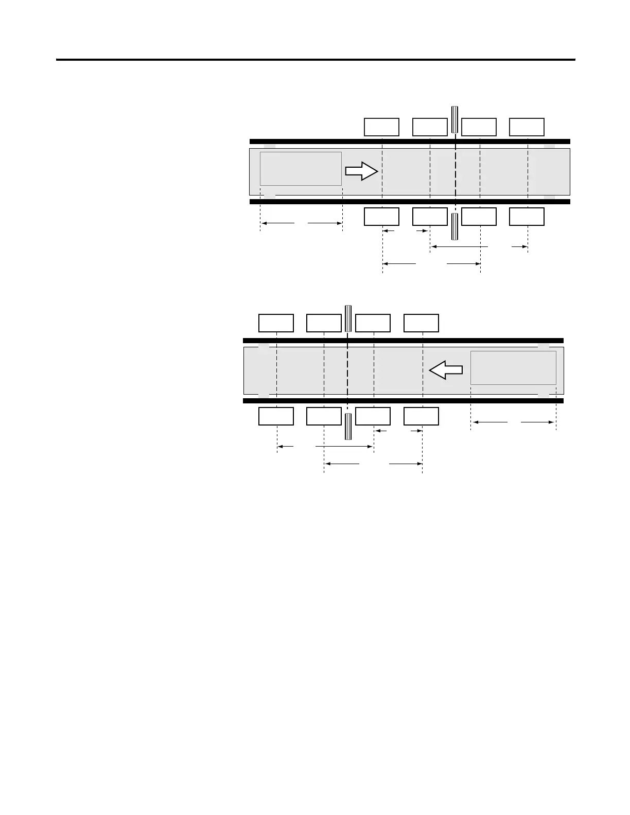
Application Setup
Sensor 11 is connected to Muting Signal 11. Sensor 12 is connected to
Muting Signal 12. Sensor 21 is connected to Muting Signal 21. Sensor
22 is connected to Muting Signal 22.
Muting Sequence
The muting sequence for this example is described below.
1. The light is not interrupted between sensors 11, 12, 21, and 22
and the light curtain, so the Output Enable signal is on.
2. For the entrance, as the workpiece moves to the right and
sensors 11 and 12 go on in order (sensors 21 and 22 go on as
the workpiece exits), muting is enabled and the muting signal
turns on.
3. As the workpiece continues to advance, the Output Enable
signal is kept on even if the light curtain is obstructed.
Sensor 11
Workpiece
L
V
Sensor 11
Sensor 12
Sensor 12
Sensor 21
Sensor 21
Sensor 22
Sensor 22
d2
D3
D2
Entrance
Sensor 11
Workpiece
L
V
Sensor 11
Sensor 12
Sensor 12
Sensor 21
Sensor 21
Sensor 22
Sensor 22
d2
D3
D2
Exit
Light Curtain
Light Curtain

 Loading...


