Publication 1752-UM001A-EN-P - October 2006
198 Function Blocks Command Reference
Override Timeout During Override
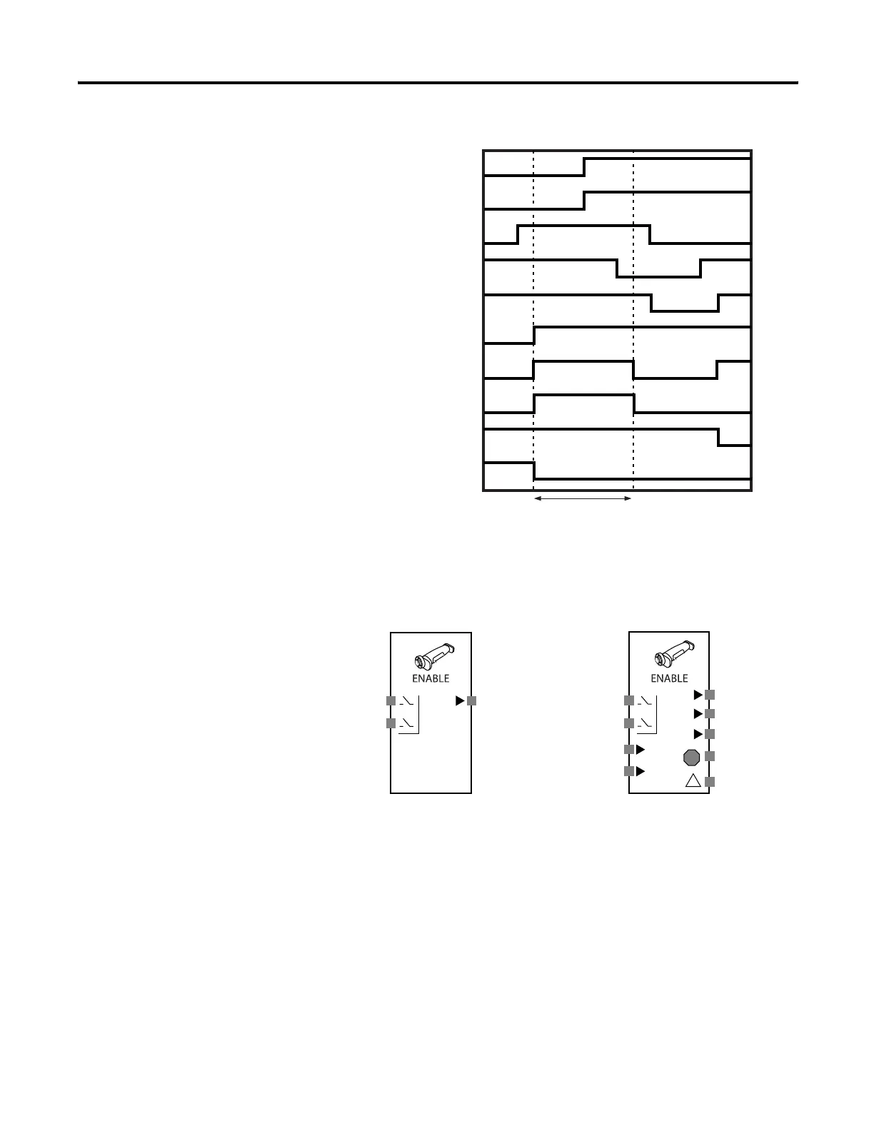
Enable Switch
Enable Switch Block Diagram
The enable switch function block monitors the status of the
enable-switch device. The Output Enable signal is on when the inputs
from the monitored enable-switch device are active. The Output
Enable signal is off when the inputs are not active or an error is
detected in the function block.
In addition, if the enable switch device is the type that outputs a grip
signal and a release signal, the device’s grip input and release input
signal status can be monitored. The received grip input and release
input signals do not affect the status of the Output Enable signal.
AOPD Input 1 (NC)
AOPD Input 2 (NC)
Muting Signal 11
Muting Signal 12
Output Enable
Override Sequence
Max. Override Time
Override Input 1 (NO)
Fault Present
Muting Status
Sequence Error
!
!
Input 1 (NO)
Output Enable
Default Connections Maximum I/O for Enable Switch Function
Fault Present
Input 2 (NO)
Output Enable
Grip Enable
Release Enable
Discrepancy Error
Input 1 (NO)
Input 2 (NO)
Grip Input
Release Input

 Loading...


