Publication 1752-UM001A-EN-P - October 2006
Application and Configuration Examples 221
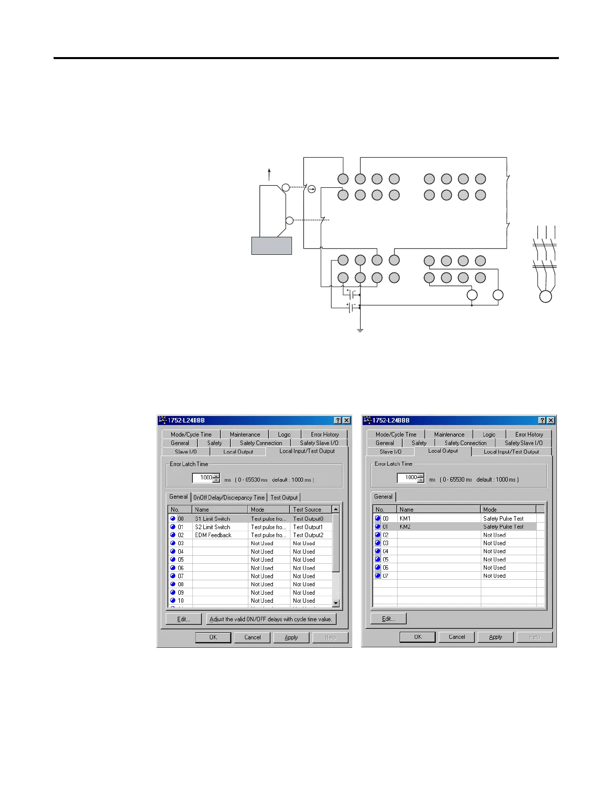
Safety Gate Application
with Automatic Reset
This example shows dual channel mode limit switches with automatic
reset.
Wiring Diagram
Configuration
V1
G1 T0
T1
I1
I0
I3
I5
I2
I4
I6
I7
T2
T3
E1
S1
O1
O0
V2 G2
O3 O5
O2 O4 O6
O7
E2
KM1
KM2
KM1
KM2
I9
I8
I11
I13
I10
I12
I14
I15
KM1-NC
KM2-NC
S2
M
Open
E1 and E2: 24V dc Power Supplies
S1: Safety Limit Switch
S2: Limit Switch (N.O. Contact)
KM1 and KM2: Contactors
Connect a 24V dc power supply to terminals V0 and G0, the power supply terminals for internal
circuits.

 Loading...


