Publication 1752-UM001A-EN-P - October 2006
Logic Functions Command Reference 151
Routing Instruction
The Routing instruction routes one input signal to a maximum of eight
output signals. It is used to output a signal to more than one physical
address, such as an output tag. The number of outputs can be set
using the I/O Setting tab in the Function Block Properties dialog. The
default setting is one.
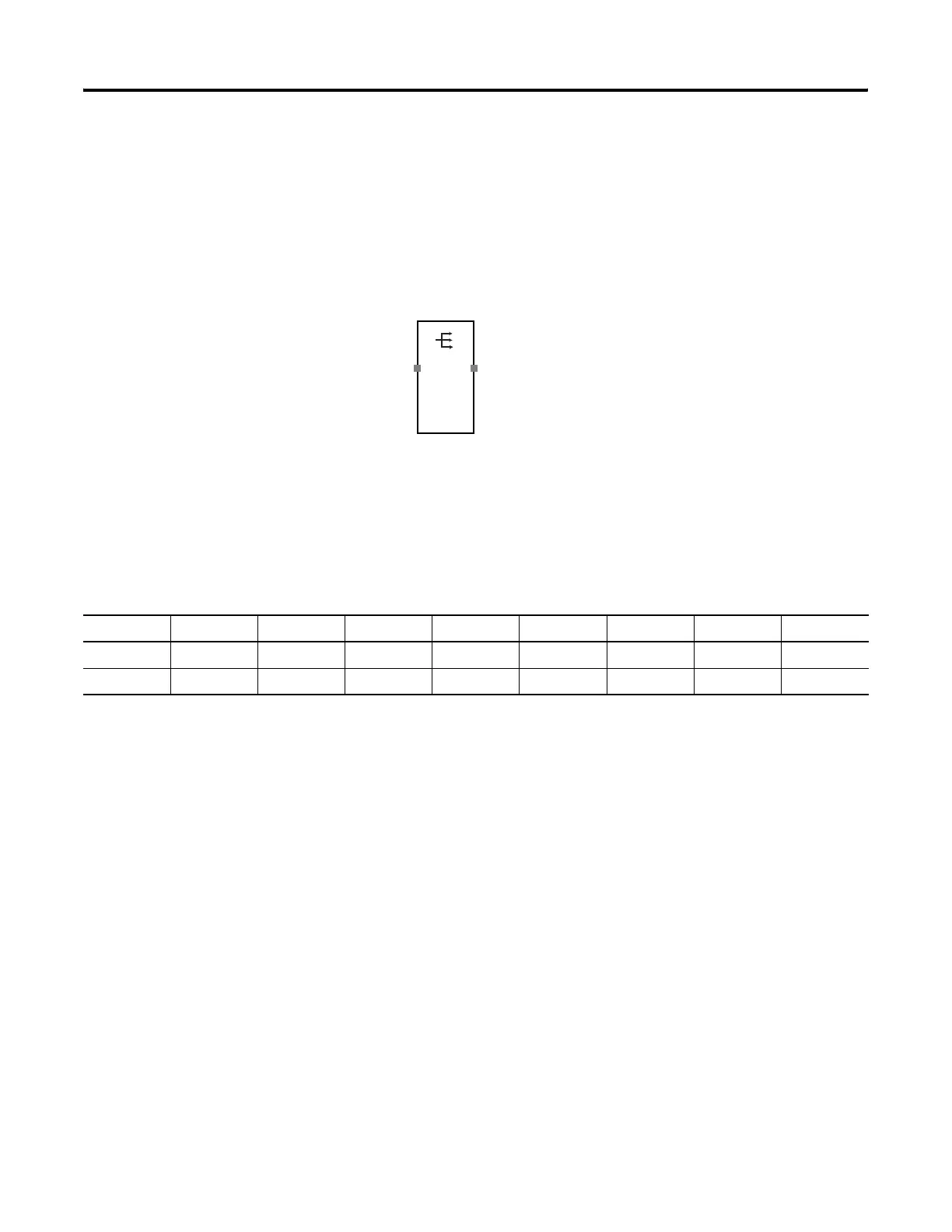
Routing Instruction Diagram
Routing Instruction Truth Table
In the truth table, 0 is off and 1 is on.
Reset Set Flip-flop (RS-FF)
Instruction
When the input signal is on, the Output Enable signal is turned on.
The Output Enable signal stays on even if the input signal turns off.
When the Reset signal is on, the Output Enable signal turns off.
A Fault Present output can also be used in programming. To enable
this optional output, check the Use Fault Present checkbox on the I/O
Settings tab of the Function Block Properties dialog in RSNetWorx for
DeviceNet software.
Output 1Input 1
Truth Table for Routing Evaluation
Input 1 Output 1 Output 2 Output 3 Output 4 Output 5 Output 6 Output 7 Output 8
0 0 0 0 0 0 0 0 0
1 1 1 1 1 1 1 1 1

 Loading...


