III-9
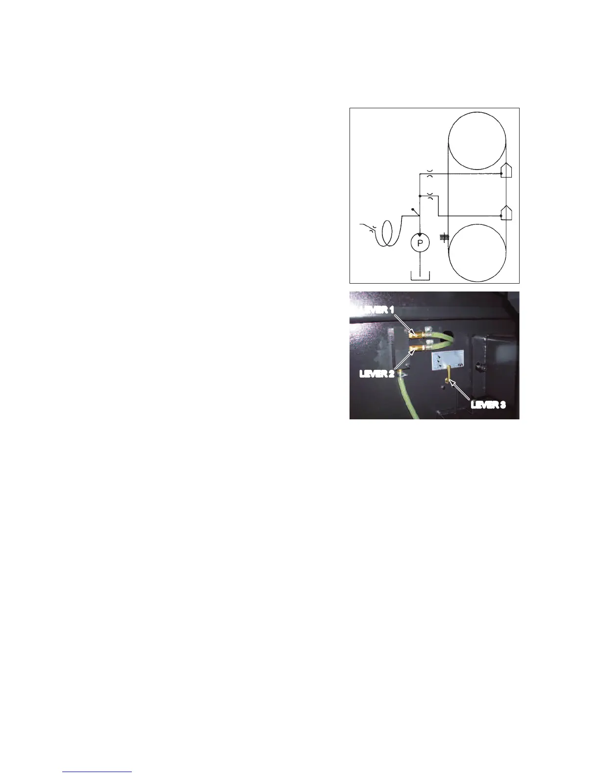
CUTTING FLUID SUPPLY SYSTEM
Th
e cutting fluid delivered
from its pump is
discharged through the
upper saw blade guide
nozzle A, lower saw blade
guide nozzle B, and
cleaning hose nozzle C.
djust the flow rate through
the nozzles with the three
cock levers near the
stairway of the bed.
A
B
C
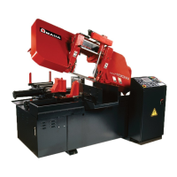
The lever 1 adjusts the flow
rate through the nozzle A.
This is designed to cool
and lubricate the saw
blade. Adjust the flow
rate to suit the work
material type and cutting
rate.
The lever 2 adjusts the flow
rate through the nozzle B.
This is designed to clear
the saw blade and wire
brush of chips. Discharge
as much cutting fluid as
possible.
LEVER 1
LEVER 2
LEVER 3
The lever 3 adjusts the flow rate through the nozzle C. Turn the lever
to the left to supply the cutting fluid to the nozzles A and B and to the
right to supply the cutting fluid to the nozzle C.