Epica DGX SC Optical Boards
116
Instruction Manual – Enova DGX 8/16/32/64 Digital Media Switchers
System Setup with DGX Fiber Modules
Epica DGX SC Optical Input and Output Boards must be used in conjunction with AMX DGX Fiber TX and RX
Modules. Compatible DGX Fiber Modules are listed on page 115. System setup options are listed in a table on page 34.
For module installation details, see the module’s Quick Start Guide or Instruction Manual.
Note: Along with the video signal, the DGX SC Optical Boards support embedded digital audio and analog
stereo audio from the DGX Fiber Modules. When installed in an Enova DGX Switcher, these boards do not
support serial data or control.
When the TX / RX Modules are installed, image adjustment and EDID scaling is automatically applied. For almost
every installation, the automatic features on the modules result in a quality image on the monitor. If the installation has
special requirements and needs additional adjustment or if you need product specifications for the modules, refer to the
Instruction Manual – DGX Transmitters & Receivers at www.amx.com
.
The distance from a DGX Fiber TX Module to a DGX SC Optical Input Board can be up to 3,000 feet (914.4 m) and
another 3,000 feet (914.4 m) from the DGX SC Optical Output Board to the DGX Fiber RX Module. For specifications
details, see page 115.
Important: Signals which are not supported are: HDCP, 3D formats, any other video signal above
1920x1200, Deep Color, and any audio signals originating in a format other than 2 channel PCM digital or
analog stereo audio. When HDCP protected video signals are routed through fiber, the display provides a
dark red image to indicate the authentication process failed. When compressed audio signals are routed, the
display goes blank. Non-HDCP signals are accepted.
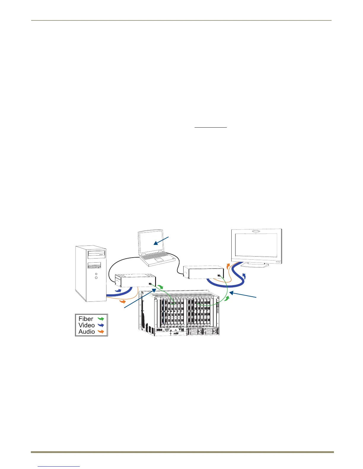
The system setup in FIG. 65 illustrates DGX SC Optical Boards used in conjunction with DGX Fiber Modules. The
DGX HD-15 TX and the DGX DVI TX Modules can be installed interchangeably.
DGX HD-15 RX and the DGX DVI RX Modules are interchangeable as well, providing for an extremely flexible
system. For example, in the same system the source device can send a DVI signal and the destination device can receive
an RGBHV signal.
Tip: For systems with special requirements – Before installing in the final location, place the equipment close
together, so the Control PC and the destination monitor can be seen simultaneously if adjustments are
necessary.
FIG. 65 SC Optical Boards are used in conjunction with DGX Fiber Modules
Source Device
Destination
DGX RX
DGX TX
USB
Control
PC
Control PC for setup –
only necessary for systems
SC fiber
up to 3000 ft.
Device
SC fiber
up to 3000 ft.
with special requirements
Enova DGX 32 with
(914 m)
(914 m)
SC Optical Boards
 Loading...