Enova DGX DVI Boards
83
Instruction Manual – Enova DGX 8/16/32/64 Digital Media Switchers
Attaching Cables
Viewed from the rear of the enclosure, the input boards (for attaching sources) are on the left, and the output boards (for
attaching destinations) are on the right.
Enova DGX 8/16 – Input and output channel numbers correspond to the connectors and are located between the input
and output boards. For inputs, numbering is consecutive from left to right on each board from the top board to the bottom
one; outputs start over at “1” and follow the same pattern.
Enova DGX 32 – Input and output channel numbers correspond to the connectors and are located on the numbering
plate (metal strip) directly above the boards. For inputs, numbering is consecutive from top to bottom on each board
from the left board to right one; outputs start over at “1” and follow the same pattern.
Enova DGX 64 – Input and output channel numbers correspond to the connectors and are located in the middle of the
enclosure between boards on either side. For inputs, numbering is consecutive from left to right on each board from the
top input board on the left to the bottom input board on the left, continuing on the top input board on the right to the
bottom input board on the right. Outputs are in the lower part of the enclosure, start over at “1” on the left, and follow the
same pattern.
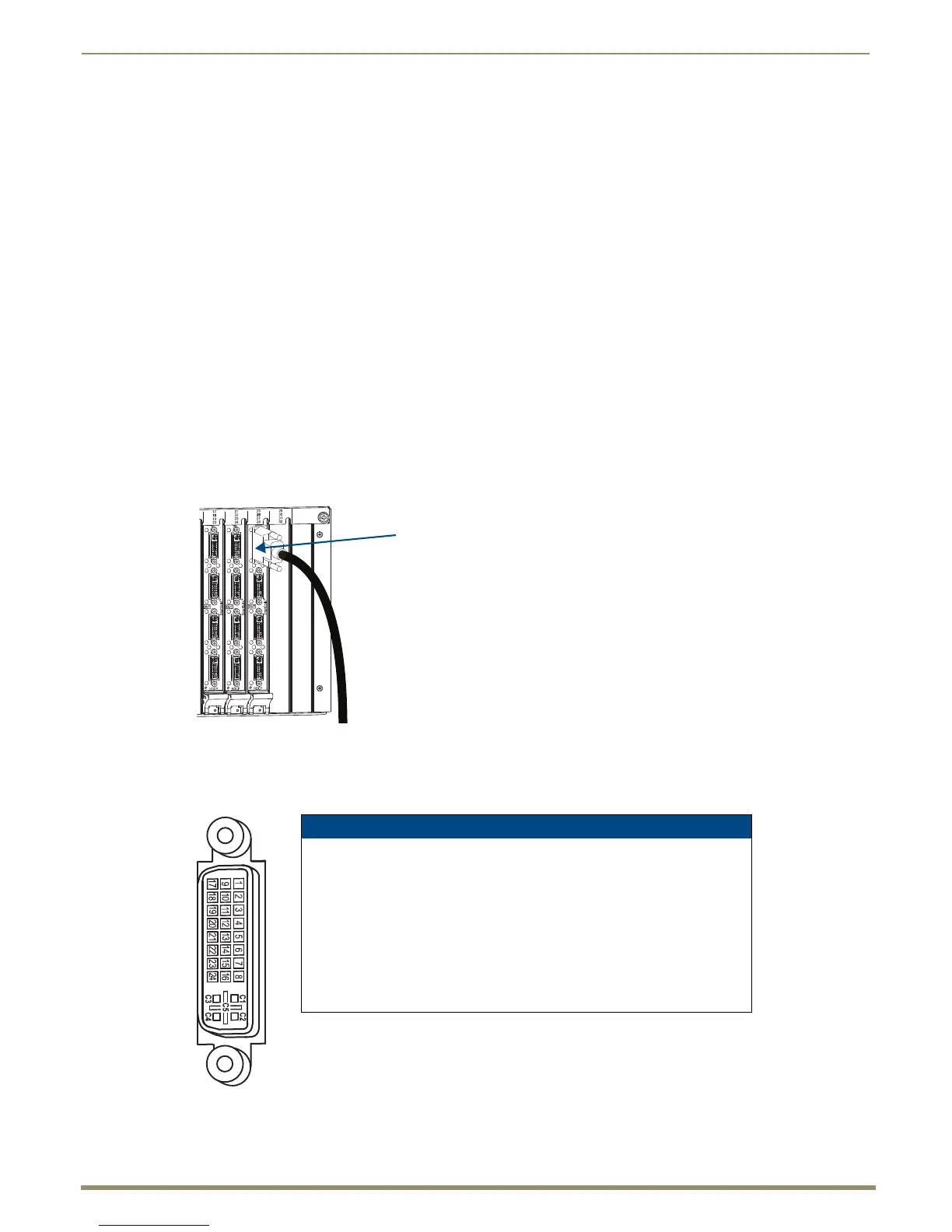
Important: We strongly recommend screwing down the DVI connector retention screws to ensure as good of
a seating of the cable into the receptacle as possible.
To connect DVI inputs and outputs:
1.
Fasten the DVI-I (or DVI-D) connectors on the cable ends onto the DVI-I receptacles on the boards.
(For DVI pinout information, see below.)
DVI Pinout
Pinout information for the DVI-I connector on the DVI Input and Output Boards is listed in the chart in FIG. 45.
FIG. 44 Fasten cables onto input and output connectors
FIG. 45 DVI-I connector pinout
* DVI output pin 14 (+5 VDC out) supplies 50 mA per each of the four output connectors.
DVI-I Pinout
1. Data 2- 9. Data 1- 17. Data 0- C1. No connect
2. Data 2+ 10. Data 1+ 18. Data 0+ C2. No connect
3. Ground 11. Ground 19. Ground C3. No connect
4. No connect 12. No connect 20. No connect C4. No connect
5. No connect 13. No connect 21. No connect C5. No connect
6. DDC-CLK 14. +5 V* 22. Ground
7. DDC-Data 15. Ground 23. CLK+
8. No connect 16. Hot-Detect 24. CLK-
 Loading...