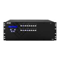
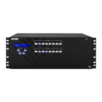
Epica DGX SC Optical Boards
117
Instruction Manual – Enova DGX 8/16/32/64 Digital Media Switchers
Safety Recommendations for Laser Products
Important: No user serviceable parts are included inside Enova DGX enclosures; service should only be
done by qualified personnel.
Exercise caution when installing Epica SC Fiber products to avoid direct eye exposure to invisible laser radiation.
Follow the recommendations below whenever installing or working with Epica SC Fiber products.
Be sure to apply the power only after all fiber connections are made and no fiber ends are exposed.
Do not remove dust plugs from Epica SC fiber connectors or the dust caps from the fiber cables until
establishing connections; avoid direct eye exposure.
Make sure all cables, including fiber cables, are correctly connected and/or terminated.
Before you unplug a fiber cable on an input board, disconnect the power on the DGX TX that is connected to
the input.
Before you unplug a fiber cable on an output board, disconnect the switch for that output connector.
Attaching Cables
Viewed from the rear of the enclosure, the input boards (for attaching sources) are on the left, and the output boards (for
attaching destinations) are on the right.
Enova DGX 8/16 – Input and output channel numbers correspond to the connectors and are located between the input
and output boards. For inputs, numbering is consecutive from left to right on each board from the top board to the bottom
one; outputs start over at “1” and follow the same pattern.
Enova DGX 32 – Input and output channel numbers correspond to the connectors and are located on the numbering
plate (metal strip) directly above the boards. For inputs, numbering is consecutive from top to bottom on each board
from the left board to right one; outputs start over at “1” and follow the same pattern.
Enova DGX 64 –
Input and output channel numbers correspond to the connectors and are located in the middle of
the enclosure between boards on either side. For inputs, numbering is consecutive from left to right on each board
from the top input board on the left to the bottom input board on the left, continuing on the top input board on the
right to the bottom input board on the right.
Outputs are in the lower part of the enclosure, start over at “1” on the left,
and follow the same pattern.
Note: Instructions for attaching cable management bars are on page 39. These bars are recommended and
provided with each DGX SC Optical Board.
Check When Fastening Fiber Cables:
Make sure that no dust or debris is on the exposed ends of the fiber cable.
Make sure that the fiber cable connectors seat firmly into the board and module fiber connectors.
(Normally an audible click is heard when a connector engages.)
Caution: Use of controls or adjustments or performance of procedures other than those specified herein
may result in hazardous radiation exposure.
Caution: Do not severely bend or kink the SC fiber cable. Irreversible damage can occur. Refer to the
physical limitations (bend radius) specified for the cable. The bend radius for AMX SC terminated fiber
cables is 2 inches (5 cm).
 Loading...