Appendix F – Program Run Disable Mode
225
Instruction Manual – Enova DGX 8/16/32/64 Digital Media Switchers
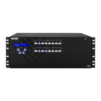
6. Set the Position #1 DIP switch to ON (places the integrated Master into PRD mode).
Note that the DIP switch is mounted with the ON position toward the bottom of the board.
7. Slowly slide the CPU board back into the empty slot, being careful to align the edges in the board guides along the
insides (FIG. 131).
8. Push the CPU board into the enclosure firmly enough to make a good electrical connection (avoid pushing on the
connectors). When fully inserted, the faceplate on the CPU board should sit flush with the back metal.
9. Reattach the faceplate to the enclosure with the two screws that were removed in Step 3.
10. Plug in both AC power cords.
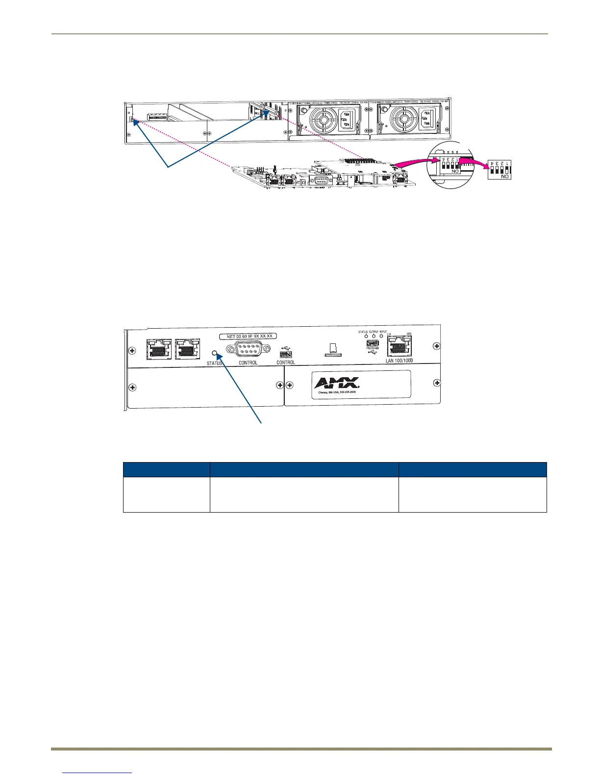
11. Check the System Status LED on the CPU for indications of normal display (see the table below).
* A system is in IOS mode when an unexpected, temporary, critical error is trapped and logged and control is passed to the
host software (IOS) which prevents the normal appcode from running until the error is manually cleared. Please report all
such errors to technical support (see page 69).
12. Re-attach the cables that were removed in Step 2.
13. Execute a test switch to make sure the system is working correctly (see page 56).
14. Use NetLinx Studio (v3.5.960 or later) to resolve the communication and/or control problems with the resident
NetLinx program.
15. Download the corrected program.
16. Follow Steps 1 through 13 again for removing the CPU board and resetting the DIP switch.
This time, on Step 6, reset the Position #1 DIP switch to OFF (places integrated Master back into Normal mode).
17. Try communication and/or control again.
Note: For CPU troubleshooting information, see page 228.
FIG. 131 Set Position #1 DIP switch to ON
FIG. 132 Check System Status LED indicator
CPU LED Indicator Normal Display Cautionary Display
System Status Constant green during power up, then blinking green
at 1/2 second on/off intervals (this applies whether
the Master is in Normal mode or PRD mode)
• Blinking red/green: an exception has
been logged in IOS (validation failure)
• Blinking red: dropped into IOS mode*
PRD mode
Normal mode
Board guides
DIP switch
 Loading...